The part looked correct when it came out of the mold.
The ribs were filled. The surface appeared clean. No flash. No burn marks.
Then quality checked it several hours later.
One mounting point had moved. A flat sealing surface was no longer flat, and the distance between two critical holes had shifted beyond tolerance.
The molding machine had completed its cycle. But the part was not finished changing.
This is a common challenge in PA66-GF30 injection molding. The material offers the stiffness, strength, heat resistance, and structural performance required for demanding automotive and industrial components. At the same time, it reacts strongly to moisture, fiber orientation, wall-thickness changes, gate location, packing conditions, and cooling imbalance.
Small process differences can become dimensional problems.
A part may leave the tool within specification and move later as internal stresses relax or moisture content changes. Another part may remain stable but show different dimensions across cavities. Sometimes one side pulls inward. Sometimes an entire frame twists.
The answer is not one machine adjustment.
Reliable dimensional control comes from treating resin drying, part design, tool design, process settings, cooling, conditioning, and inspection as one connected system.
Why PA66-GF30 Is Used for Demanding Molded Components
PA66-GF30 is polyamide 66 reinforced with approximately 30% glass fiber by weight. The reinforcement increases stiffness, strength, creep resistance, and dimensional stability compared with an unfilled nylon.
That makes the material useful for components that must carry load, maintain geometry, or survive elevated temperatures.
Common applications include:
- Automotive electrical housings
- Battery-module components
- Busbar carriers
- Structural brackets
- Connector bodies
- Cooling-system parts
- Under-hood components
- Industrial frames and covers
The material can replace metal in selected applications while reducing weight and integrating features into one molded component.
But the glass fibers create directional behavior.
The polymer matrix and the fibers do not shrink in exactly the same way. Fibers align as the melt flows through the mold, and the final part becomes anisotropic. In plain terms, its properties and shrinkage behavior may differ depending on direction.
That is where warpage starts.
Drying Comes Before Dimensional Control
PA66 is hygroscopic. It absorbs moisture from the surrounding air.
The resin may arrive in moisture-resistant packaging, but once the container is opened, exposure begins. Open bags, uncovered hoppers, long material-transfer paths, and humid production environments can all affect the condition of the pellets before molding.
Moisture is not only a cosmetic concern.
When wet polyamide is processed at molding temperature, the combination of moisture and heat can reduce molecular weight through hydrolytic degradation. The material may still fill the cavity, but its mechanical performance and process consistency can be affected.
Possible warning signs include:
- Surface streaking
- Splay or silver marks
- Reduced viscosity
- Unstable fill behavior
- Weak mechanical properties
- Flash at previously stable settings
- Increased dimensional variation
- Brittle molded features
Sometimes there is no obvious visual warning.
That makes moisture control a process requirement, not a troubleshooting option.
Use the Resin Supplier’s Drying Specification
There is no single drying time or temperature that should be copied across every PA66-GF30 grade.
The correct condition depends on:
- Resin formulation
- Initial moisture level
- Packaging condition
- Dryer design
- Dry-air dew point
- Airflow
- Material-bed depth
- Residence time
- Supplier recommendations
A standard grade, heat-stabilized grade, hydrolysis-resistant grade, flame-retardant grade, or impact-modified grade may have different processing requirements.
Always use the current technical datasheet for the exact resin.
Do not assume two materials are interchangeable because both labels say PA66-GF30. Additives, flow characteristics, stabilization packages, and recommended processing windows can differ.
The dryer must also be verified.
A temperature display alone does not prove that the material is dry. The system needs adequate dry-air quality, airflow, residence time, and proper return-air performance.
If the dryer is operating but the dew point is poor, the pellets may stay warm and still retain too much moisture.
Warm is not the same as dry.
How to Control Material Handling After Drying
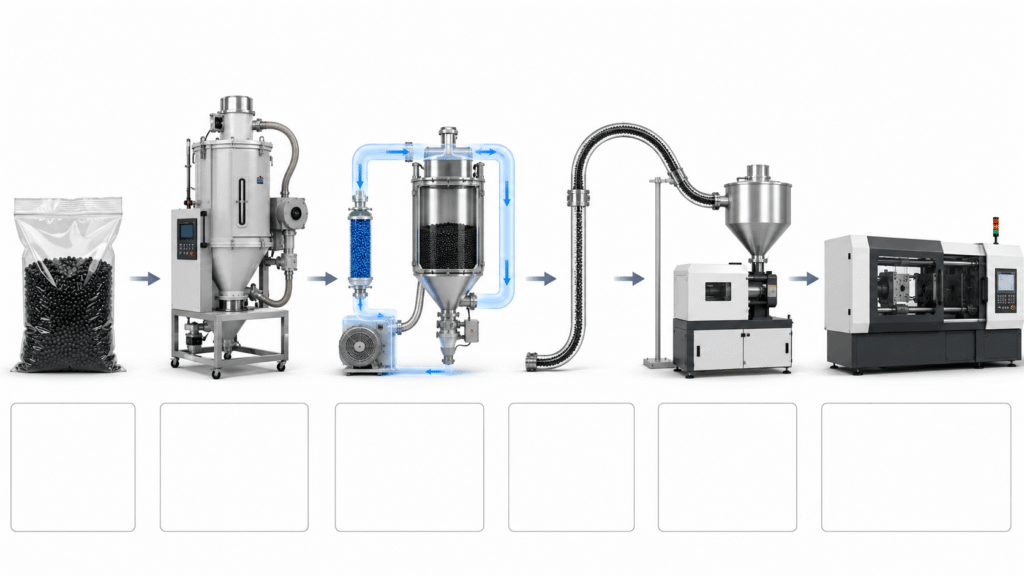
Correct drying can be lost quickly through poor handling.
Once the resin leaves the dryer, it should remain protected until it enters the machine. Long open transfers, uncovered containers, and material left in the hopper through extended shutdowns can reintroduce moisture.
A controlled handling plan may include:
- Keeping resin packaging sealed until use
- Recording material lot numbers
- Using a properly sized desiccant dryer
- Monitoring dryer temperature and dew point
- Limiting material exposure during transfer
- Using closed conveying where practical
- Managing hopper residence time
- Re-drying material when required by the approved procedure
Production teams should also define what happens after a line interruption.
If the press stops for several hours, can the material remain in the hopper? Should it return to the dryer? Does the barrel need purging?
Those decisions should already be documented.
Why PA66-GF30 Warps
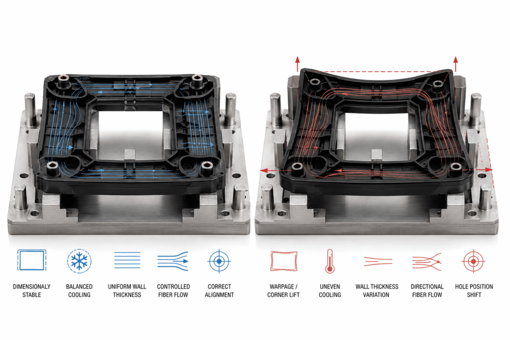
Warpage occurs when different areas of the molded component shrink, cool, or relax by different amounts.
PA66-GF30 makes the issue more complex because glass fibers align with melt flow. Shrinkage parallel to the fibers differs from shrinkage across them.
The part does not contract uniformly.
Imagine a rectangular carrier with ribs, bosses, clips, and connector walls. Melt enters through the gate and divides around several features. Fibers follow those flow paths.
One region may contain fibers aligned along the length of the component. Another region may contain fibers turning around a hole or meeting at a weld line.
When the part cools, each region responds differently.
The result may be:
- Bowing
- Twisting
- Corner lift
- Out-of-flatness
- Hole-position shift
- Uneven boss height
- Connector misalignment
- Assembly interference
Warpage is not always caused by excessive overall shrinkage. Often, it is caused by uneven shrinkage.
Fiber Orientation Is a Design and Process Variable
Fiber orientation begins with the filling pattern.
Gate location, gate size, injection speed, wall thickness, flow direction, ribs, openings, and weld lines all influence how fibers align.
A gate placed for easy tool construction may create a poor flow pattern.
The cavity may still fill, but the part can distort after ejection.
For glass-filled parts with tight tolerances, gate design should be evaluated based on more than fill pressure and cycle time. The engineering team must consider how melt flow will orient fibers across critical dimensions.
Questions to ask include:
- Does flow travel symmetrically through the part?
- Do fibers align differently on opposite sides?
- Are critical mounting points located near flow transitions?
- Does the gate create strong orientation around a flat surface?
- Will two flow fronts meet near a loaded feature?
- Can the filling pattern be balanced with another gate strategy?
Mold-flow simulation can help predict filling, packing, fiber orientation, cooling, shrinkage, and warpage before steel is finalized.
It does not remove the need for molding trials.
It gives the team a better starting point.
Part Design Has a Direct Effect on Warpage
Uniform wall thickness remains one of the most important design rules in injection molding.
Thick sections cool more slowly than thin sections. They also require more packing and can shrink differently after ejection.
In PA66-GF30, abrupt thickness changes can also redirect flow and change fiber orientation.
Common design risks include:
- Thick mounting pads attached to thin walls
- Heavy boss bases
- Deep ribs
- Large solid corners
- Uneven frame sections
- Sudden wall transitions
- Asymmetrical reinforcement
- Long unsupported surfaces
Ribs should add stiffness without creating unnecessarily thick intersections. Bosses should be supported while avoiding heavy material concentration at the base.
A part can be structurally strong and still be difficult to mold within tolerance.
Design for stiffness and design for molding must work together.
Mold Temperature and Cooling Balance
Mold temperature affects surface replication, flow, crystallization, internal stress, and dimensional behavior.
An unstable mold temperature creates an unstable part.
If one side of the cavity runs hotter than the other, cooling and shrinkage become uneven. The part may pull toward the hotter side or release with internal stress that appears later.
Cooling channels should provide balanced heat removal around critical features.
Potential problems include:
- Cooling lines too far from the cavity surface
- Uneven channel spacing
- Restricted water flow
- Scale inside cooling circuits
- Different flow rates between mold halves
- Hot spots around thick sections
- Poor cooling near slides or inserts
- Different inlet-water temperatures
A machine may display the correct mold-controller setpoint while actual steel temperatures vary across the cavity.
That is why periodic thermal checks matter.
The objective is not simply a cold mold. It is a stable and balanced mold.
Running the mold too cold can create other problems, including poor surface quality, increased frozen-in stress, difficult filling, and inconsistent packing.
Packing Pressure and Hold Time
Packing compensates for material shrinkage while the gate remains open.
Too little packing can produce sinks, voids, inconsistent dimensions, and weak feature definition. Excessive packing can create high residual stress, flash, difficult ejection, and dimensional distortion.
Hold time also matters.
Once the gate freezes, additional holding pressure no longer packs the cavity effectively. It may only increase machine time.
A proper gate-seal study helps determine the point at which additional hold time stops increasing part weight.
Part weight is useful here.
If weight continues increasing as hold time increases, the gate is still transmitting pressure. When weight stabilizes, gate seal has likely occurred.
The goal is not the highest possible part weight. It is a stable part produced inside an approved dimensional and mechanical window.
Injection Speed Can Change Fiber Orientation
Injection speed influences shear, flow-front behavior, pressure, and fiber alignment.
A speed that is too low may allow premature freezing, hesitation, poor weld lines, and unstable filling. A speed that is too high may increase shear heating, fiber breakage, jetting, burn marks, or orientation effects.
Most complex parts do not need one constant speed through the entire fill.
A staged profile may be better.
The process can slow near gates or sensitive features, accelerate through long flow sections, and reduce speed as the cavity approaches full.
But every change should have a reason.
Do not add multiple speed stages just because the machine allows it. A complicated recipe can hide the real process.
Ejection Can Create Distortion
The part is still hot and relatively weak when it leaves the mold.
If ejection force is unbalanced, a dimensionally correct component can be bent during release.
Common causes include:
- Insufficient draft
- Rough tool surfaces
- Uneven ejector-pin placement
- Small ejector contact areas
- Part sticking to one mold half
- Excessive packing
- Early ejection
- Weak support around large flat areas
The component may spring back partially, but not completely.
Ejection marks can reveal the problem. Sometimes the distortion appears only after the part rests.
A longer cooling time may help, but the real solution may be improved draft, polishing, ejector layout, or packing control.
Post-Molding Moisture Changes Dimensions
Dry-as-molded PA66 does not necessarily have the same dimensions as conditioned PA66.
After molding, the component begins absorbing moisture from the environment. Moisture affects dimensions and mechanical properties.
That means measurement timing must be defined.
A dimension checked immediately after molding may differ from the same dimension measured after conditioning or environmental exposure.
The control plan should specify:
- When parts are measured
- Whether parts are dry-as-molded or conditioned
- Conditioning method
- Storage temperature and humidity
- Time between molding and inspection
- Packaging requirements
- Customer measurement condition
Without that agreement, the supplier and customer can measure the same part and get different results.
Both readings might be technically correct. They were just taken under different conditions.
Tolerance Control Starts With a Clear Measurement Strategy
A drawing tolerance is only useful when the measurement method is repeatable.
PA66-GF30 parts may include flexible walls, complex datums, clips, ribs, and surfaces that move under probing or fixture pressure.
Measurement variation can be confused with molding variation.
A strong inspection plan defines:
- Datum structure
- Fixture method
- Probe force
- Measurement temperature
- Conditioning state
- Time after molding
- CMM program revision
- Sampling frequency
- Cavity identification
Critical dimensions should be reviewed by cavity and over time.
Combining all cavities into one dataset can hide a cavity-specific issue.
If cavity three consistently runs near the upper limit while the others remain centered, the tool may need local correction even though the overall process still passes.
A Practical Warpage Troubleshooting Sequence
When a PA66-GF30 part moves out of tolerance, avoid changing five machine settings at once.
Use a controlled sequence.
1. Confirm the Measurement
Verify the fixture, datum, conditioning state, and inspection method.
2. Check the Material
Confirm the resin grade, lot, drying record, dryer condition, and material-handling history.
3. Compare Cavities
Determine whether the issue affects every cavity or one specific cavity.
4. Review Part Weight
Weight variation can point toward inconsistent filling, packing, gate seal, or material condition.
5. Inspect Mold Temperature
Check actual steel temperature and cooling-circuit performance.
6. Review Filling and Packing
Evaluate fill time, transfer position, cushion, peak pressure, hold pressure, and gate seal.
7. Inspect Ejection
Look for sticking, uneven ejector marks, insufficient draft, and part deformation during release.
8. Change One Variable
Make one documented adjustment and compare the result with the previous condition.
Simple. Slow. Controlled.
That approach usually works faster than random tuning.
Holding Tight Tolerances in High-Volume Production
A capable development trial is not enough.
High-volume production introduces normal variation in material lots, ambient humidity, tool wear, dryer performance, cooling flow, machine condition, and operator activity.
The process needs controls that detect drift before parts fail inspection.
These may include:
- Resin-lot traceability
- Dryer temperature and dew-point monitoring
- Recipe control
- Cushion monitoring
- Fill-time limits
- Peak-pressure limits
- Part-weight checks
- Mold-temperature verification
- Cavity-specific dimensional data
- Preventive mold maintenance
- Defined reaction plans
The team should know what to do when a trend changes.
Stop the process? Adjust it? Quarantine parts? Check the dryer? Inspect one cavity?
The response should not depend on who is standing near the machine.
Frequently Asked Questions
Does PA66-GF30 Need to Be Dried Before Molding?
Yes. PA66 is moisture-sensitive and should be processed according to the drying requirements of the exact material grade. Dryer temperature, dry-air quality, residence time, and material handling all matter.
What Causes Warpage in PA66-GF30 Parts?
Common causes include uneven fiber orientation, unbalanced cooling, wall-thickness variation, gate location, inconsistent packing, residual stress, and post-molding moisture absorption.
How Does Glass Fiber Affect Shrinkage?
Glass fibers reduce overall shrinkage but make shrinkage directional. The part can shrink differently parallel and perpendicular to fiber orientation, increasing the risk of warpage.
Can Higher Packing Pressure Eliminate Warpage?
Not always. Packing can improve dimensions when insufficient compensation is the cause, but excessive pressure can increase residual stress and create new distortion.
Why Do PA66-GF30 Dimensions Change After Molding?
The part continues cooling and relaxing after ejection. It can also absorb moisture from the environment, which may affect dimensions and properties.
Should PA66-GF30 Parts Be Measured Immediately?
Measurement timing must follow the customer specification and control plan. Dry-as-molded and conditioned parts may produce different dimensional results.
Can Mold-Flow Simulation Predict Warpage?
Simulation can help predict filling, fiber orientation, cooling, shrinkage, and warpage. Final tool trials and physical measurements are still required.
How Can Cavity-to-Cavity Variation Be Controlled?
Use balanced filling and cooling, verify cavity geometry, track dimensions by cavity, monitor part weight, and maintain the mold according to a controlled schedule.
Build Dimensional Accuracy Into the Entire Process
PA66-GF30 tolerance control does not begin at final inspection.
It begins with dry material.
Then comes part design, gate location, fiber orientation, mold temperature, packing, cooling, ejection, conditioning, and measurement.
Every stage leaves a mark on the final dimensions.
Haumann Group supports precision PA66-GF30 injection molding for demanding automotive and industrial applications. Our team works with customers on material selection, DFM, tooling, process validation, cavity-level quality control, and scalable production.
CTA Button: Discuss Your PA66-GF30 Project