High-volume injection molding works by making many identical parts in every machine cycle: a multi-cavity steel mold — at Haumann, from 4 to 32 cavities — is filled in one shot, cooled under control, and emptied by automation, while real-time statistical process control (SPC) watches every cycle. For programs running from 100,000 to more than 10 million parts a year, the difference between a supplier who can quote a low unit price and a supplier who can actually hold it is not the press. It is the engineering done before the steel is cut: design for manufacturability (DFM), balanced multi-cavity tool design, a stable process window, and inspection evidence that follows every batch.
This guide walks through the full process in plain language: what counts as high volume, how DFM changes when you design for scale, how a multi-cavity tool is designed and balanced, where cycle time really goes, how automation and SPC keep millions of parts alike, which materials suit high-volume work, which defects appear at scale and how to prevent them, and when to move from pilot to mass production. It is written for engineers, product managers and sourcing teams who need to brief a manufacturer — or judge one.
If you already have a proven part and want the short route, start with Haumann’s high-volume injection molding services, where the supported volume range, tooling, materials and quality controls are set out in one place.
What counts as high volume — and when it pays off
At Haumann, high-volume programs typically run from 100,000 units to over 10 million components a year, using multi-cavity tooling from 4-cavity up to 32-cavity configurations with automated robotics. That range is the working definition for this guide — but volume alone does not decide whether high-volume tooling is the right call. Three things have to be true at the same time.
First, the design has to be stable. A multi-cavity tool multiplies whatever is in the design — including any mistake. A wall that sinks, a gate that leaves a weld line on a stressed surface, or a tolerance tighter than the function needs will not appear once per cycle; it will appear in every cavity, every cycle, for the life of the program. That is why high-volume work starts with a DFM review, not with a tooling quote, and why the cheapest moment to fix a problem is still before the steel is machined.
Second, the economics have to favour tooling over piece price. A multi-cavity production tool costs more up front than a single-cavity or prototype tool, and it pays that back only across a long run: more parts per cycle, less machine time per part, and less handling per part. If annual demand is uncertain, or the design is still changing, a bridge tool or a lower cavity count is usually the honest recommendation. Blog #4, “High Volume vs Low Volume Injection Molding: Cost, Tooling & When to Scale“, covers that cost comparison in full — this guide does not re-explain its cost curves, and links to it where the volume decision is discussed.
Third, the program has to be able to absorb the discipline that scale demands. Long runs need documented process windows, material certificates mapped to batches, batch-level inspection and change control — the unglamorous work that keeps part number one million the same as part number one. If a buyer only needs a few thousand parts, that discipline is overhead. At a million parts, it is the product.
Haumann’s model for this kind of program is US engineering with Asia-scale production: project ownership, DFM and communication managed from Houston, Texas, with production able to scale through Asia capacity under one quality standard. That structure matters at high volume, because the engineering conversation stays close to the buyer while the capacity behind it can run long, automated shifts.
DFM for scale: design decisions that multiply
DFM — design for manufacturability — is the same discipline at any volume, but at high volume every decision is multiplied by the cavity count and the run length. The high-volume page puts it plainly: most production issues are designed in early and discovered too late, and a proactive DFM-first methodology is how engineering teams isolate and prevent the common failure modes before they become scrap.
The review starts with the part design, not the mold. Engineers check wall thickness and uniformity, draft angles for clean release, gate locations, parting lines, ribs, bosses and any undercuts that would need slides or lifters. At scale, two of those checks carry extra weight. Wall thickness drives cooling time, and cooling time drives cycle time, so a wall that is thicker than the function needs does not just add material — it adds seconds to every cycle, multiplied by millions of cycles. And fibre orientation in glass-filled compounds such as PA66-GF30 — one of Haumann’s high-volume materials — affects shrinkage and warpage direction, so gate placement has to be planned with fibre flow in mind, not just with fill in mind.
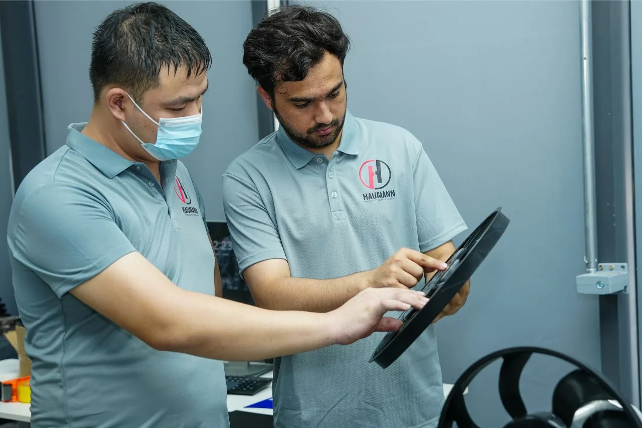
The DFM review is not a one-off check before tooling. Haumann describes it as the entry point to a project: a technical review that produces specific, actionable feedback — wall corrections, rib adjustments, gate moves — before any steel is ordered. Done this way, DFM sets the cavity count, the runner balance, the cooling layout and the SPC plan all at once, which is why the review has to happen early. Fixing a gate position on paper costs nothing; moving it in hardened steel costs a tooling revision and a program delay.
The tolerance scheme gets the same treatment. The review asks which dimensions are truly critical, and which are tighter than the function requires and will only add tooling and inspection cost. At high volume, an unnecessarily tight tolerance is not a one-off cost: it is extra inspection, extra process adjustment and extra rejected parts on every shift. A good DFM review gives specific, drawable changes with reasons — not a vague promise that the part will be fine — and Haumann’s page records the deliverables as technical DFM feedback with actionable mold design optimization changes, plus tooling concept risk reviews covering gating configurations and venting paths.
The next check is material compounding. For high-load and wear-resistance targets, the exact commercial grade is specified, certificates are collected, and lot traceability is planned from the start — because a material family name is not a specification, and swapping grades mid-program can invalidate the evidence behind a product file. The materials Haumann lists for high-volume work are engineering-grade thermoplastics: PA66-GF30, PBT, PC/ABS blends, and structural elastomers such as TPU and TPEE. Each is chosen against the job the part must do — strength, stiffness, impact, heat, chemical exposure — and each brings its own processing behaviour that the tool and process window must respect.
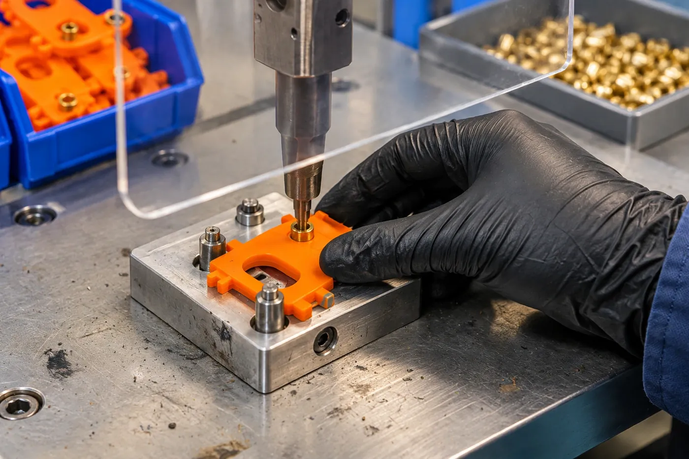
A final DFM point that buyers often miss: secondary operations should be designed in, not bolted on. If a part needs inserts, overmolding, assembly, functional testing or pack-out, those steps are cheapest when the part, the tool and the cell are planned together. Haumann offers automated product assembly at scale, custom overmolded assemblies, dynamic functional testing and pack-out-ready fulfilment — but even where a buyer does finishing elsewhere, the molded part should arrive designed for it.
Multi-cavity tool design: balance is everything
The mold is a precision steel tool machined to form the cavities and cores of the part, with runners, gates, cooling channels and ejection built in. In a multi-cavity tool, one shot fills several cavities at once — at Haumann, 4 to 32 of them — and the central engineering challenge is balance: every cavity must fill at the same time, at the same pressure, and with the same temperature profile. If one cavity fills before the others, the result is over-packing, flash, short shots or dimensional variation between cavities that should be identical.
Runner balance is how that is achieved. In a naturally balanced runner, every cavity sits at the same flow distance from the sprue, usually through a symmetrical H-pattern or radial layout, so the flow path length and resistance are identical for every cavity. Where natural balance is impractical — mold size, part geometry, or an awkward cavity count — engineers use artificially balanced runners, adjusting runner diameters to equalise flow resistance, and they verify the result with mold-flow simulation before steel is cut. The key point for a buyer is not which layout was chosen, but that balance was simulated and then proven at sampling: first parts are measured cavity by cavity, not just as an average, because an average can hide one bad cavity.
Gate design sits alongside runner balance. Each cavity needs its own gate, and gate type — edge, pin, hot tip — affects cycle time, cosmetic finish and whether manual degating is needed. Gate location decides where weld lines fall, and at high volume a weld line on a stressed or visible surface is a defect repeated millions of times, so gate placement is a DFM decision, not a toolmaker’s afterthought. For an independent, detailed walkthrough of runner balance, gate sizing and cooling layout, ZetarMold’s guide to designing multi-cavity molds and CLF’s multi-cavity injection molding guide are both useful references.
Hot runner versus cold runner is the other big tooling decision. A hot runner keeps the polymer molten inside a heated manifold, so there is no cold runner to regrind or discard, and each gate gets more consistent temperature control. That matters more as cavity count rises: with eight or more cavities, the runner waste from a cold runner system becomes a real cost and a real source of variation. Haumann’s high-volume tooling uses hot runner configurations as standard for production programs. Cold runners still have a place — simpler tools, lower up-front cost — but for a long, multi-cavity run, the hot runner usually earns its place back in material saved and consistency gained.
Tooling classification and steel are the durability decisions. Haumann designs and builds SPI Class 101 multi-cavity tooling for high-volume programs, using premium tool steels such as H13 or P20, with specialised coatings to withstand millions of cycles. Class 101 is the highest SPI classification, built for high-volume production — and that matters because a high-volume tool is not just a bigger single-cavity tool. It is a tool that must hold its dimensions across millions of cycles, with cooling, ejection and venting that stay balanced as the tool wears. The tooling agreement Haumann describes — framing SPI mold classifications, real-time cavity process parameters, inline dimensional quality checkpoints and change control before production steel is machined — is exactly the paperwork that protects a buyer when a program runs for years.
Cavity count: what each band is for
The right cavity count is a program decision, not a bigger-is-better contest. More cavities mean more parts per cycle and a lower unit cost — but they also mean a larger, more complex tool, tighter balance requirements, and more cavities to qualify and monitor. The table below is qualitative guidance for the conversation with a supplier, using only Haumann’s verified 4–32 cavity range. It is not a price list, and it does not promise a cycle time or a unit cost — those depend on the part, the material and the machine, and they belong in a quoted program plan.
| Cavity band | Typical fit | What to watch |
|---|---|---|
| 4–8 cavities | First step into true multi-cavity production; parts moving from pilot into steady annual volumes | Balance is straightforward, qualification is fast; unit cost falls sharply versus single-cavity, but machine time per part is still material |
| 8–16 cavities | Established high-volume programs with a stable design and predictable demand | Hot runner is usually justified here; cooling balance across cavities becomes as important as fill balance; cavity-by-cavity sampling is essential |
| 16–32 cavities | Long-running, high-volume programs where unit cost and output per shift dominate the economics | Tooling complexity and qualification effort are at their highest; SPC must be watched cavity by cavity, and any design change is expensive — so DFM must be settled first |
If a supplier proposes a cavity count without asking about annual volume, design stability, part size and material, that is a warning sign. The count should follow the program, not lead it.
The molding cycle at scale: where cycle time really goes
Production molding runs a repeating cycle. Plastic pellets are dried where the resin requires it, fed into a heated barrel, melted and mixed by a rotating screw, then injected under pressure into the closed mold. Pressure is held while the part packs out and begins to cool, cooling continues until the part is stable enough to eject, and ejector pins release it. The cycle then repeats. For most parts of this type the cycle is measured in seconds, depending on size, wall thickness and material — and at high volume, every fraction of that cycle is multiplied by the number of cycles in the program.
Cooling is usually the largest share of cycle time, which is why so much high-volume engineering is really cooling engineering. Wall thickness, gate location, cooling-channel layout and mold temperature all decide how fast heat leaves the part evenly — and evenly is the operative word. Uneven cooling creates warpage and differential shrinkage, so parts from different cavities can end up with different final dimensions even if they filled identically. Each cavity should have its own dedicated cooling thinking, and thermal imaging during mold qualification can reveal hot spots before they become production problems. That is why Haumann’s DFM and tooling work includes cavity thermal balance assessments and mold-flow simulations, run from pilot trial validations up to full-scale deployment.
The other phases matter too, and they interact. Injection speed and pressure decide fill and weld-line placement. Hold time decides packing and sink. Ejection decides whether a part releases cleanly or is stressed on the way out. Repeatability comes from holding the process window — melt and mold temperatures, injection speed and pressure, hold time and cooling time are set during validation and monitored in production — not from inspecting quality in afterwards. A process window that is defined, logged and held is what lets a program run across shifts, operators and months without drifting.
Cycle-time improvement at scale is therefore a sequence, not a single trick: DFM first (thin where the function allows, uniform walls, sensible gates), then tooling (balanced runners, effective cooling, hot runner where justified), then process (a validated window, not a fast guess), then automation (handling that does not add seconds or damage parts). A supplier who promises a faster cycle by turning up one machine setting is describing the most expensive way to learn that the window was not stable.
For a general background on how the molding cycle itself works, Plastics Technology’s injection molding topic hub is a useful industry reference, as it was for Blog #5.
Automation: the cell around the press
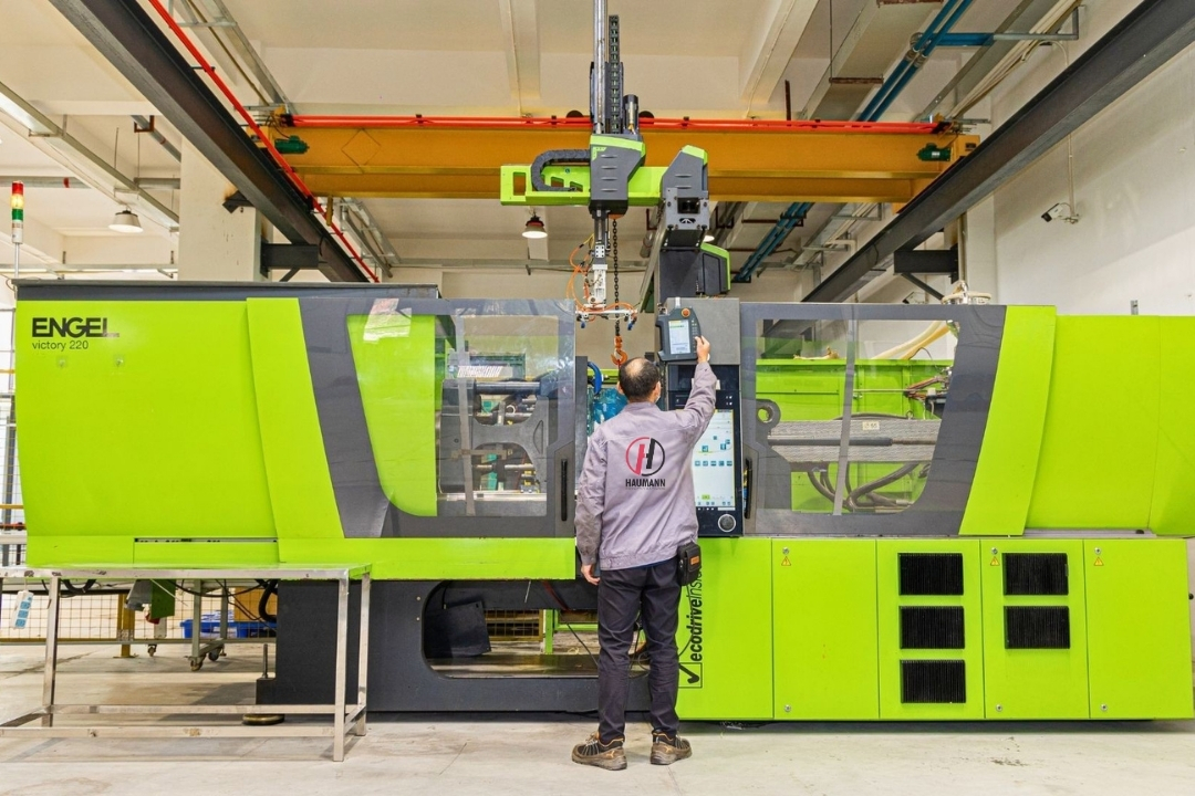
At high volume, the press is only half the cell. Multi-axis robotics, optical end-of-arm tooling and automated handling decide whether parts leave the mold cleanly, are placed or stacked without damage, and arrive at pack-out with their identity intact — and whether the cycle time the tool was designed for is the cycle time the program actually achieves. Haumann’s high-volume capabilities list integrated automation explicitly: high-speed multi-axis robotics and optical end-of-arm tooling for optimised cycle efficiency and high part yield.
Automation earns its place in three ways. First, it removes the handling variation that creeps in when people unload a fast-cycling tool by hand — a part placed differently is a part cooled differently, and at scale that shows up as dimensional drift. Second, it protects the part: hot, thin-walled or cosmetic parts are easily marked by manual handling, and a mark repeated a million times is a quality escape, not a handling accident. Third, it makes the cell measurable — robot, press and inspection can share a cycle record, so when a dimension drifts, the team can see whether the press, the tool or the handling changed.
But automation is not a substitute for a good process. It is the precision amplifier of a process that is already stable — and in a stable cell, the robot repeats exactly what the tool and the process produce, cycle after cycle. The same controlled approach applies across Haumann’s plants, which is how output and quality stay consistent when a program moves between the United States and Asia capacity.
The honest caveat is that automation does not fix a bad process. A robot will faithfully unload a warped part a million times. That is why automation is sequenced after DFM, tooling and process validation in this guide, not before them — and why the qualification of a high-volume cell includes the robot, the end-of-arm tooling and the handling path, not just the mold.

Quality at scale: SPC cycle by cycle, CMM batch by batch
Quality at high volume is a system, not an inspection step. Haumann’s approach, as described on the high-volume page, is a strict DFM-first methodology coupled with real-time statistical process control: injection pressure profiles, barrel temperature zones and cavity cooling curves are monitored cycle by cycle, so defects such as warpage, sink marks, flash or short shots are detected and prevented before parts leave the tool. That is the core idea — prevention in the process, not sorting at the end of the run.
SPC works because it watches the process, not just the part. A pressure trace that starts to drift, a cooling curve that changes shape, or a cavity that begins to behave differently from its neighbours are all visible in the data before they become out-of-tolerance parts. The process window logs Haumann describes — defined process window logs for continuous and highly predictable production output — are the record that makes that possible: the window is written down, the process is held to it, and any change is a documented decision, not a quiet adjustment on a night shift.
Batch-level validation sits alongside SPC. Rigorous batch-level Coordinate Measuring Machine (CMM) inspections, raw material certificate mapping and full statistical validation logs are how a batch is released — Haumann’s page lists exactly those three, together with inline dimensional quality checkpoints during production. The pattern is the same as Blog #5’s medical guide: first-article checks on sampled parts, in-production dimensional and cosmetic checks, and documented correction when a dimension drifts. At high volume, the difference is frequency and traceability: material lots, production batches, inspection results and packing identity should connect, so that if a question arises months later, the history of the component can be reconstructed.
Haumann operates under ISO 9001 and IATF 16949 certified quality systems, with the measurement, inspection and traceability discipline those systems require. The same care about scope applies here as in Blog #5: this guide makes no ISO 13485 or cleanroom claim for high-volume work, and buyers should always match a supplier’s certificates to the exact scope of their own program. The automotive plastic components program runs under IATF 16949 discipline for Tier 1 and Tier 2 suppliers, and high-volume buyers benefit from the same habits — documented control, measurement and traceability — applied to their own scope.
Materials for high-volume molding
There is no single best high-volume plastic. The right choice follows the application: what the part must carry, how hot it gets, what chemicals it meets, whether it must be stiff or flexible, and what documentation the buyer’s file needs. The table below summarises the materials Haumann lists for high-volume work. It is a starting point for a DFM conversation, not a substitute for grade-level selection and testing on the finished part — the exact commercial grade, certificates and lot traceability are always specified per program.
| Material | Common high-volume uses | Why it is chosen | Watch out for |
|---|---|---|---|
| PA66-GF30 (glass-filled nylon) | Structural brackets, housings, load-bearing parts | Strength, stiffness and wear resistance from the glass fibre | Fibre orientation affects shrinkage and warpage — gate placement and DFM must account for it; drying is essential |
| PBT | Electrical housings, connectors, precision parts | Dimensional stability, chemical resistance, good electrical properties | Processing window and drying need control; gate and cooling design matter for flatness |
| PC/ABS | Enclosures, covers, housings needing toughness and finish | Toughness of PC with the processability and finish of ABS | Chemical exposure and stress cracking must be checked for the application |
| TPU / TPEE | Grips, seals, flexible and overmolded features | Flexibility, grip and sealing at volume | Grade selection drives feel, durability and bond to the substrate in overmolding |
For a deeper, independent overview of material selection, the Plastics Technology injection molding topic hub is a useful starting point, and the multi-cavity guides linked in the tooling section above cover how each material’s flow behaviour affects runner and gate design. The regulatory frame, where it applies to a buyer’s product, is always the finished device or assembly — material data sheets support a file, they do not complete it.
Defects at scale: prevent them, do not sort them out
Most molding defects are process messages. Each one points to a cause in design, material preparation or machine settings — and each one should become rarer as a program matures, because the cause gets engineered out. At high volume, the stakes are higher because a defect is multiplied by the cavity count and the run length. These are the defects high-volume buyers most often ask about, and what prevents them. The failure modes below are the same ones Haumann’s DFM-first review is designed to isolate early: warpage, sink marks, flash, short shots, weld-line strength issues, fibre-orientation distortion and unstable dimensional tolerances across long runs.
| Defect | What you see | Typical cause | Prevention |
|---|---|---|---|
| Warpage | Part twists or bows after ejection | Uneven cooling or shrinkage, poor gate placement, fibre orientation | Balanced cooling, gate review and mold-flow thinking in DFM; thermal balance across cavities |
| Sink marks | Dips on the surface over thick sections | Uneven wall thickness or insufficient packing | Uniform walls in DFM; ribs instead of solid thickness; correct hold time and pressure |
| Flash | Thin excess plastic along the parting line | Worn tooling, low clamp force or excess pressure | Tool maintenance, correct clamp and process settings; SPC pressure monitoring |
| Short shots | Part is incomplete or a feature is missing | Insufficient material, pressure or venting; unbalanced runners | Correct shot size, pressure and mold venting; runner balance verified cavity by cavity |
| Weld lines | Visible line where two melt fronts meet; weak under load | Gate position, low melt or mold temperature | Gate relocation and temperature control; keep lines off stressed areas |
| Fibre-orientation distortion | Warpage or weakness that follows fibre direction (GF compounds) | Gate placement ignoring fibre flow; uneven cooling | Fibre-orientation analysis in DFM; gate and cooling design that respect flow direction |
| Tolerance drift | Dimensions wander across a long run | Process window drift, tool wear, material lot change | SPC cycle-by-cycle monitoring; batch CMM checks; documented change control |
Notice the pattern: most prevention happens before production — in DFM, material selection, tooling and process setup. Inspection confirms that prevention worked. A supplier who talks mainly about final inspection is describing the most expensive and least reliable way to run a high-volume program.
Scaling checklist: from pilot to mass production
Moving from pilot to mass production is a decision with a checklist, not a date on a calendar. Use this list before committing to a multi-cavity production tool.
- Design frozen, or frozen enough: the part has been through DFM, the changes are drawn, and the tolerance scheme names the dimensions that truly matter.
- Material specified by grade: the exact commercial grade, its certificates and its lot traceability are agreed — not just the material family.
- Tooling concept reviewed: cavity count, runner balance, gate types, cooling layout, SPI Class 101 classification and steel grade are documented, with mold-flow and thermal-balance work done before steel is cut.
- Process window defined: melt and mold temperatures, injection speed and pressure, hold and cooling times are set during validation and logged — not left to operator memory.
- SPC and inspection agreed: which parameters are monitored cycle by cycle, which dimensions are checked in production and at batch CMM, and what happens when a result is out of tolerance.
- Automation and handling qualified: robot, end-of-arm tooling and pack-out are part of the qualification, not added after the mold is approved.
- Secondary operations planned: assembly, overmolding, testing and packaging are designed in, with lot identity preserved through to delivery.
- Change control agreed: who approves a tool, material or process change, and how it is recorded — because at high volume, an undocumented change is a quality escape waiting to happen.
Haumann’s program steps, as set out on the high-volume page, follow the same order: consultation and global program alignment with final CAD analysis and annual volume targets; a manufacturing agreement and quality control plan locking SPI classifications, cavity process parameters, inline checkpoints and change control before steel is machined; automated production execution with multi-axis robotics and real-time monitoring; and technical quality validation with batch CMM, material certificate mapping and statistical validation logs before logistics handover. If a supplier cannot walk you through those four steps for your part, the program is not ready to scale — however good the unit price looks.
How to choose a high-volume molding partner
Use this checklist when you compare suppliers. The best partner will answer every point with evidence, not adjectives.
- Ask for a written DFM review with specific design changes and reasons before you commit to tooling — and ask what changed as a result of it.
- Confirm the cavity count reasoning: why this count, for this annual volume, this part and this material — not just that more cavities are available.
- Ask how runner balance and cooling balance were simulated, and how they will be proven cavity by cavity at sampling.
- Ask what SPC is monitored cycle by cycle, and what the batch CMM and release process looks like — then ask to see a sample record.
- Confirm the exact resin grades proposed, the certificates and lot traceability that come with them, and the drying and handling discipline behind them.
- Check that certificates match the scope: ISO 9001 and IATF 16949 discipline is valuable, but it is not a substitute for the evidence your own product file needs.
- Confirm who owns project communication, where they sit, and how changes are documented — and confirm that proprietary CAD models, tool blueprints and process parameters are protected under NDA, as Haumann describes.
- Compare total program cost — tooling, unit price, finishing, freight and the cost of a quality escape — not unit price alone.
In short: high-volume injection molding is won before the first production shot — in the design review, the tool design, the process window and the quality system. Choose the partner who proves control at those stages, and the molding itself becomes the most predictable part of your program. If you are preparing a part for 100,000 to 10 million units a year, send the design for an engineering-led DFM review and get a manufacturing plan you can put in front of your own quality team with confidence. Start with Haumann’s high-volume injection molding services, or contact the Houston team at globalsales@haumann-group.com or +1 (832) 497-0809.
Short, direct answers to the questions engineers and sourcing teams ask most often about high-volume programs.
Frequently Asked Questions: How High-Volume Injection Molding Works
Start with a DFM review of your part
Share the part design for an engineering-led review covering manufacturability, material options, tooling strategy and quality planning for your high-volume program. Explore the scope first on Haumann’s high-volume injection molding services page, or contact the Houston team at globalsales@haumann-group.com or +1 (832) 497-0809.