Injection molding defects are messages, not mysteries. A sink mark, a warped part, flash on the parting line or a short shot each points to a specific cause — in the part design, the material, the mold or the process settings — and each one should become rarer as a program matures, because the cause gets engineered out. This guide explains the four defects buyers ask about most, what each one looks like, what usually causes it, and what actually fixes it, so you can tell a one-off from a problem that will repeat on every run.
The short version: most defects are designed in before molding starts. A thick section will sink. Uneven cooling will warp. A mold that does not close cleanly, or a process pushed too hard, will flash. A mold that does not fill will short. The fix is almost never a single machine setting on its own — it is a combination of DFM review, tooling, material preparation and a held process window, in that order. If a supplier can only offer one of those, the defect will come back.
The four defects at a glance
| Defect | What you see | Most common causes | Where the fix usually lives |
|---|---|---|---|
| Sink marks | A shallow dip or dimple on the surface, usually opposite a rib, boss or thick section | Thick section cooling and shrinking more than the wall around it; not enough packing | DFM (wall thickness, rib design) + packing / cooling |
| Warpage | A part that bends, twists or does not sit flat after ejection | Uneven shrinkage — one side cools or shrinks differently from the other | DFM + mold cooling balance + material and process window |
| Flash | A thin fin of plastic along the parting line, vents or ejector marks | Mold not closing fully, worn tooling, or injection pressure / speed beyond what the tool can hold | Tooling condition + process settings |
| Short shots | A part that is incomplete — a missing corner, an unfilled thin section | Not enough material reaching the cavity: fill, venting, material flow or gate problem | Tooling (gates, vents) + material preparation + process settings |
Read the table as a starting point, not a diagnosis. Two defects can share a cause, and one defect can have two causes at once — a sink mark and warpage, for example, can both come from the same uneven wall. The sections below work through each defect in turn, then explain how to prevent all four together, because in practice that is how a good program works: one DFM review, one tool, one process window.
Sink marks: a dip where the part is thickest
A sink mark is a shallow depression on the surface of a molded part, most often directly opposite a rib, a boss or another thick feature on the other side of the wall. The surface looks pulled in. On a cosmetic part — a housing, a cover, a control panel — a sink mark is a visible defect the buyer sees every day, and on a functional part it can also mean the wall is not as drawn.
Why it happens is straightforward once you picture the part cooling. Plastic shrinks as it cools. A thick section holds more material and stays hot longer than the thin wall around it, so it keeps shrinking after the surface has already set. The surface above it is pulled inward as the material underneath contracts. The thicker the section relative to its wall, the deeper the mark tends to be — which is why sink marks appear opposite ribs and bosses rather than at random.
The fix starts in design, not on the machine. A DFM review looks for exactly this: walls that change thickness abruptly, ribs that are too heavy for the wall they support, and bosses that are solid where they could be cored out. The usual design answers are to keep wall thickness as even as possible, to size ribs and bosses in proportion to the wall, and to add fillets and gradual transitions instead of sharp steps. None of that is visible in the finished part when it is done well — which is the point. A part that looks simple on the outside is often the one whose inside was designed most carefully.
Process settings matter too, and this is where a supplier earns the order. Packing — holding pressure after the cavity fills, while the part cools — feeds extra material into the thick section as it shrinks, and cooling that is even across the part lets the thick and thin sections settle together. But packing and cooling can only do so much if the design fights them. A boss that is far too heavy for its wall will sink whatever the machine does, and raising the pressure to force it only moves the problem elsewhere, often into flash or stress. That is why Haumann’s process puts the DFM geometric risk evaluation before tooling: the review finds the sink risk while a change still costs a drawing revision instead of a mold revision. Blog #8 explains the same point for appliance housings, where a sink mark on a premium cover is a rejected part.
What to ask when you see a sink mark: which feature sits opposite the mark, and what is the wall-to-feature ratio there? Was the mark present on the first samples, or did it appear as the run went on? And what changed in the DFM review to address it? If the answer is only a machine setting, ask what happens to the next thick feature on the same part.
Warpage: a part that will not sit flat
Warpage is a part that bends, twists or bows after it leaves the mold, so it does not sit flat or fit the assembly it was made for. It is often invisible until the part is tried against its mating part — a housing that rocks on a flat surface, a frame whose holes no longer line up, a cover whose edges lift. For an assembly, where several molded parts have to fit together on an automated line, warpage is not a cosmetic issue. It is an alignment problem, and it slows or stops the line it feeds.
The cause is uneven shrinkage. If one side of a part cools faster than the other, or one region shrinks more than the region next to it, the part pulls itself out of shape as it settles. The usual contributors are uneven wall thickness, cooling that is stronger on one side of the mold than the other, gate placement that fills one side before the other, and material behavior — some grades shrink more than others, and some, notably nylons such as PA66, absorb moisture, so drying and storage matter as well as the molding itself. Fiber-filled grades add another wrinkle: fibers orient with the flow, so shrinkage differs along and across the flow direction, and a part can warp in a direction the drawing never predicted.
The fix, again, is a combination. In design, even walls, balanced gates and cooling planned with the part — not just with the mold — keep shrinkage even. In tooling, cooling channels are laid out so heat leaves the part evenly; evenly is the operative word, because cooling that is fast on one side and slow on the other is itself a cause of warpage. In material preparation, the grade is dried and handled as its data sheet requires, so moisture does not add a variable the process cannot see. And in production, the process window — melt and mold temperatures, injection speed and pressure, hold time and cooling time — is set during validation and held, not left to operator memory, so a part molded this month matches a part molded last month.
For material-specific warpage, Haumann already has a dedicated guide: the PA66-GF30 drying, warpage and tolerance post covers that grade’s drying and warpage behavior in depth, and the selection logic there applies whenever a filled nylon is on the table. This post stays general on purpose — warpage in a thin ABS cover and warpage in a glass-filled structural bracket have different causes, and the grade-specific guide is the right place for the grade-specific detail.
What to ask when you see warpage: does the part warp the same way every time, or does it vary across cavities and shifts? Same-way warpage points to design, cooling or gate layout; varying warpage points to process drift or material handling. And was the first-article check done against the mating part, or only against the drawing? A part can pass its own dimensions and still fail the assembly.
Flash: a thin fin where the mold meets
Flash is a thin fin of plastic that escapes the cavity — usually along the parting line where the two mold halves meet, but also around vents, ejector pins or inserts. It feels sharp, it looks unfinished, and it has to be removed before the part can be used. On a part that must seal or fit closely, flash is also functional: it changes the dimension at the edge where it forms.
Flash happens when material finds a gap it should not have. The common reasons are a mold that is not closing fully — because of wear, contamination on the parting line, or a clamping problem — and a process pushed beyond what the tool can hold: injection pressure or speed high enough to force material into the gap between the mold halves. Both can be true at once, and both are worth checking before either is blamed. A mold that flashed only after thousands of cycles points to wear; a mold that flashed from the first shot points to setup or design.
The fix is tooling first, process second. The mold’s parting line must close cleanly and stay clean, vents must be sized and maintained so air can leave without letting plastic follow it, and worn edges must be repaired rather than worked around. Only then do process settings come into play: bringing injection speed and pressure back inside the window the tool was validated for, and checking that the shot size is not over-packing the cavity. Raising pressure to cure a short shot, for example, can create flash — the defects trade against each other, which is why changing one setting without watching the others is how a program chases its own tail.
What to ask when you see flash: where exactly is it — parting line, vent, ejector, insert? Did it start suddenly or grow gradually? And what is the tool’s maintenance history? Flash that appears late in a tool’s life is a maintenance signal, and the honest answer is a tool repair, not a quieter machine setting.
Short shots: a part that never filled
A short shot is a part that comes out incomplete — a missing corner, an unfilled thin section, a rib that never formed. It is the most obvious defect on this list, because the part is visibly not the part that was ordered, and it cannot be used. It is also the most useful defect diagnostically: a mold that does not fill is telling you, plainly, that material is not reaching the cavity.
The causes fall into three groups. First, the process: not enough material, too little pressure, or a melt that is too cool to flow to the end of the cavity. Second, the tool: a gate that is too small or in the wrong place, a flow path that is too long or too thin for the grade, or vents that are blocked so trapped air has nowhere to go and stops the flow. Third, the material: a grade that is too viscous for the wall thickness, pellets that were not dried and therefore do not flow as expected, or a material change mid-program that nobody validated. Thin walls, long flow lengths and cold molds make all three worse.
The fix follows the same order as the diagnosis. Check the material first — grade, drying, and whether anything changed since the last good run. Then the tool — gate size and position, venting, and whether the flow path suits the part. Then the process — melt temperature, injection speed and pressure, and hold time — set back inside the validated window. The order matters because the most expensive fix is not always the right one: enlarging a gate is a tool change, while a blocked vent is a cleaning job, and the two look identical until someone checks.
What to ask when you see a short shot: is the unfilled area always the same place? The same place points to a gate, vent or flow-path problem in the tool; a moving short shot points to material or process variation. And has the grade, the drying, or the supplier changed since the last good parts? A short shot that starts the week a material changes is rarely a coincidence.
Other defects you may see — and what they usually mean
The four above are the most common, but they are not the only ones. Two more appear often enough to be worth naming, briefly, so you can recognize them and ask the right question.
Weld lines (knit lines) are faint lines where two flow fronts meet and join — usually around a hole, a boss or a feature the flow had to split around. A weld line is not automatically a failure, but on a visible surface it is a cosmetic defect, and in a thin or highly loaded section it can be a weak point. Gate placement decides where weld lines fall, which is why it is planned with the visible surface in mind on consumer-facing parts, as Blog #8 describes for appliance covers.
Burn marks are dark discoloration, usually near the end of fill, where trapped air was compressed and heated until it scorched the plastic. They point to venting — air with nowhere to go — and the fix is in the vents and the fill speed, not in the material color.
If you see bubbles or voids inside a thick section, that is usually trapped air or a sink that formed internally rather than on the surface; the causes overlap with sink marks, and so do the fixes. The pattern to remember is the same for all of them: name the defect, find where it always appears, and ask what is different there — in the design, the tool, the material or the process.
How to prevent all four at once
No single setting prevents defects. Prevention is a sequence, and it is the same sequence Haumann follows on its programs — which is why this section is the most useful one in the post for a buyer comparing suppliers.
Start with DFM, before steel is cut. The DFM review is where most defects are prevented, because most of them are designed in early and discovered too late. Haumann’s process starts with an application and functional requirement review, then early feasibility trials, then a detailed DFM geometric risk evaluation — and the review gives specific, drawable changes with reasons, not a vague promise that the part will be fine. For the buyer, the practical test is simple: ask for the DFM feedback in writing, with the changes and the reasons. The review should name the sink risks, the warpage risks, the gate positions and the wall-thickness decisions, before tooling. If a supplier cannot show you what changed in your design and why, the DFM step has not really happened, and the risk it was meant to remove is still in the program.
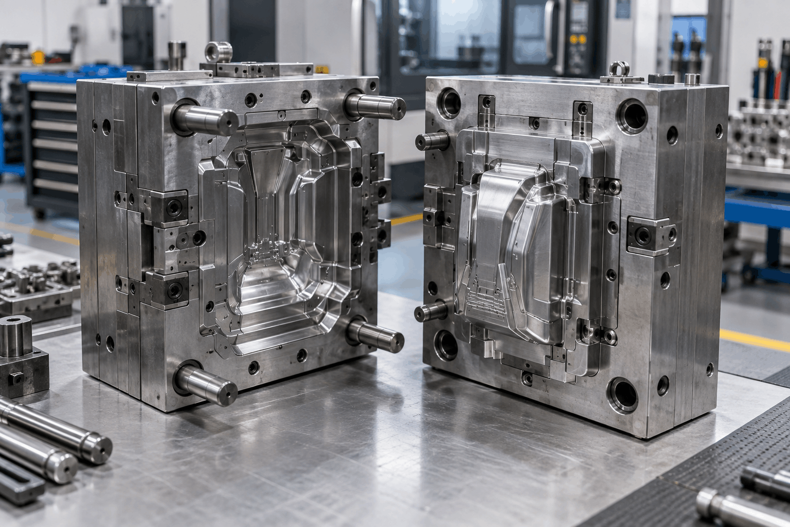
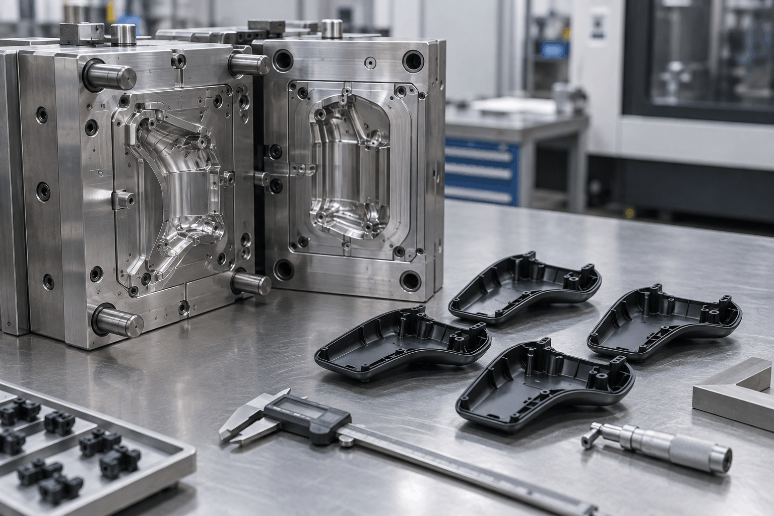
Build the tool for the program, not for the first shot. The mold is a precision steel tool, and its layout decides whether every cavity fills alike, whether cooling is even, and whether weld lines fall on a visible surface or a hidden one. Cavity balance, gate layout, cooling-channel layout and venting are planned together, with the part’s cosmetic surfaces in mind. If a supplier proposes a mold without asking about annual volume, design stability, part size and material, that is a warning sign — the tool should follow the program, not lead it. The tooling page sets out Haumann’s injection mold tooling scope; read it alongside the DFM feedback, not instead of it.
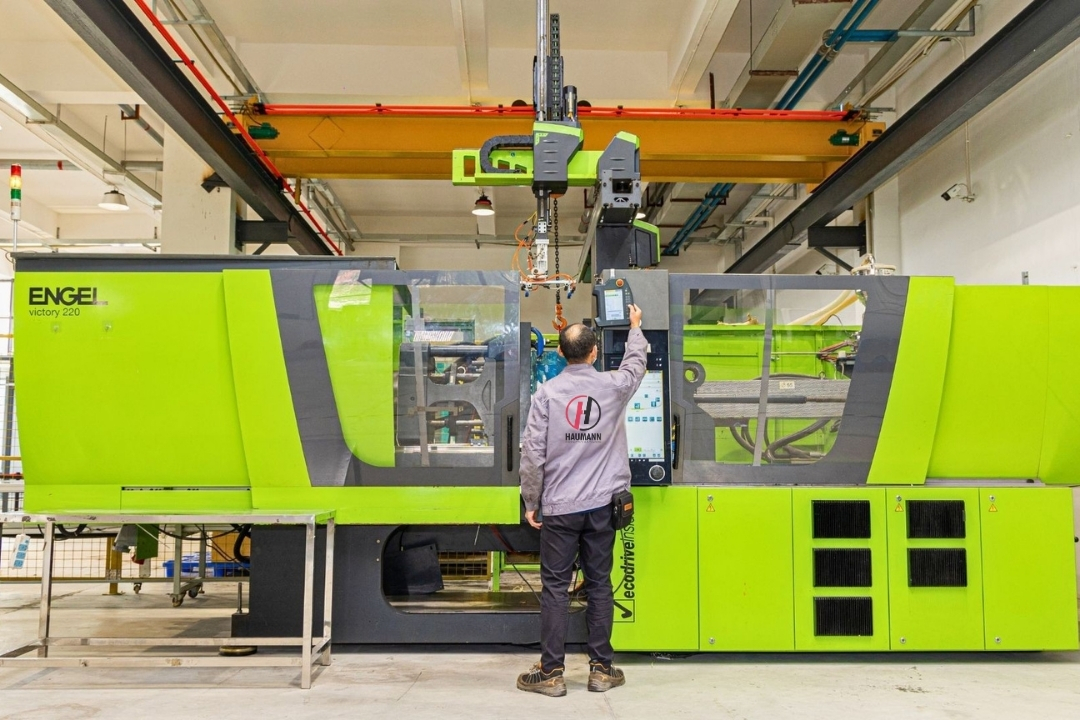
Validate, then hold the window. First samples prove the part; validation proves the process. The process window — melt and mold temperatures, injection speed and pressure, hold time and cooling time — is set during validation and held in production, with micro-level shot controls keeping the process repeatable across thousands of runs. That is the difference between a supplier who can make a good first part and a supplier who can make a good ten-thousandth part, and it is the subject of Haumann’s high-volume injection molding guide. A defect that appears mid-run, after good first samples, is usually a window that drifted, a material batch that changed, or a tool that wore — and the first question is always which of the three moved.
Check fit and finish together. Quality in molded parts is checked in layers, and the cosmetic layer is as strict as the dimensional one. A part can pass its dimensions and still fail the assembly, and a part can look right and still be short in a thin section. First-article checks should cover dimensions, surface, and fit against the mating part — not one of the three. Blog #8’s quality section makes the same point for appliance parts, where surface variations are addressed in the tooling phase and wall thicknesses are optimized through DFM validation, so the finished surfaces are pristine and match strict consumer branding standards.
What to ask a supplier before you commit
Use these questions on your next RFQ or supplier review. A good supplier answers each one with evidence, not adjectives.
- Which features on my part are the sink-mark risks, and what did the DFM review change about them?
- Where will the weld lines fall, and are they on a visible surface?
- How is cooling balanced across the mold, and how do you know it stays balanced across a long run?
- What is the validated process window, and how is it held across shifts and operators?
- How are first articles checked — dimensions, surface, and fit against the mating part?
- What happens when a defect appears mid-run: what is checked first, and who decides whether it is a tool, material or process cause?
- Can you show me a part like mine, with its defect history and what fixed it?
If the answers are specific — a rib that was thinned, a gate that was moved, a cooling layout that was changed — you are talking to a supplier that prevents defects. If the answers are general, you are talking to one that reacts to them.
Start with a DFM review of your part
Share the part design for an engineering-led review covering defect risks, material choice, manufacturability, tooling strategy and quality planning. Explore the scope first on Haumann’s high-volume injection molding page, or contact the Houston team at globalsales@haumann-group.com or +1 (832) 497-0809.
Frequently Asked Questions: Injection Molding Defects
The four buyers see most are sink marks, warpage, flash and short shots. Weld lines and burn marks are also common. Each one points to a cause in design, material, tooling or process — and each one should become rarer as a program matures.
A thick section — usually opposite a rib or boss — cools and shrinks more than the thin wall around it, pulling the surface inward. The fix starts in design (even walls, proportioned ribs and bosses) and is supported by packing and even cooling.
Uneven shrinkage: one side of the part cools or shrinks differently from the other, because of uneven walls, unbalanced cooling, gate placement or material behavior. Even walls, balanced cooling and a held process window prevent it.
Material escaping through a gap — usually a mold that is not closing fully, worn tooling, or injection pressure or speed beyond what the tool can hold. The fix is tooling first (parting line, vents, wear), then process settings back inside the validated window.
A part that comes out incomplete because material did not reach the whole cavity. Causes are process (not enough material or pressure, melt too cool), tooling (gate, vent or flow-path problem) or material (grade, drying or a mid-program change).
Sometimes a setting helps, but rarely on its own. Most defects are designed in or built into the tool, so the lasting fix is a combination of DFM, tooling, material preparation and a held process window — in that order.
A DFM review finds the risks before steel is cut — thick sections that will sink, walls that will warp, gate positions that will leave weld lines on visible surfaces — and gives specific, drawable changes with reasons, while a change still costs a drawing revision instead of a mold revision.
A weld line is a visible line where two flow fronts meet. It is not automatically a failure, but on a visible surface it is a cosmetic defect, and in a thin or highly loaded section it can be a weak point. Gate placement decides where weld lines fall.
Ask what changed since the last good parts: the process window, the material batch or drying, or the tool’s condition. A defect that appears mid-run after good first samples usually means one of those three moved.
Project ownership, engineering review and communication are managed by Haumann’s team in Houston, Texas, which directs the DFM reviews, tool configuration validations and final quality checks, while scalable offshore facilities handle high-volume mass production under one quality standard. That gives US OEM teams a local, accountable partner with global manufacturing capacity behind it.