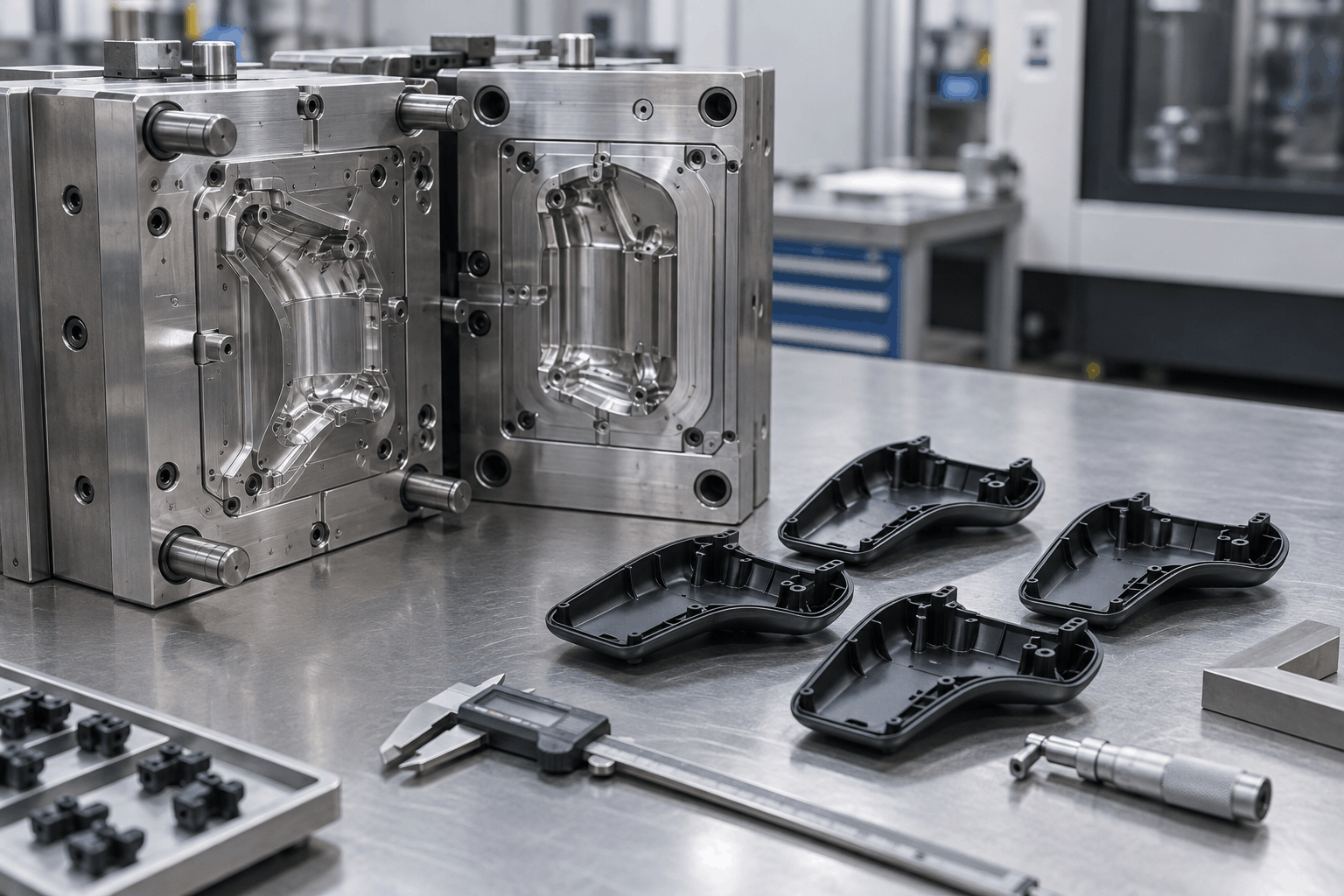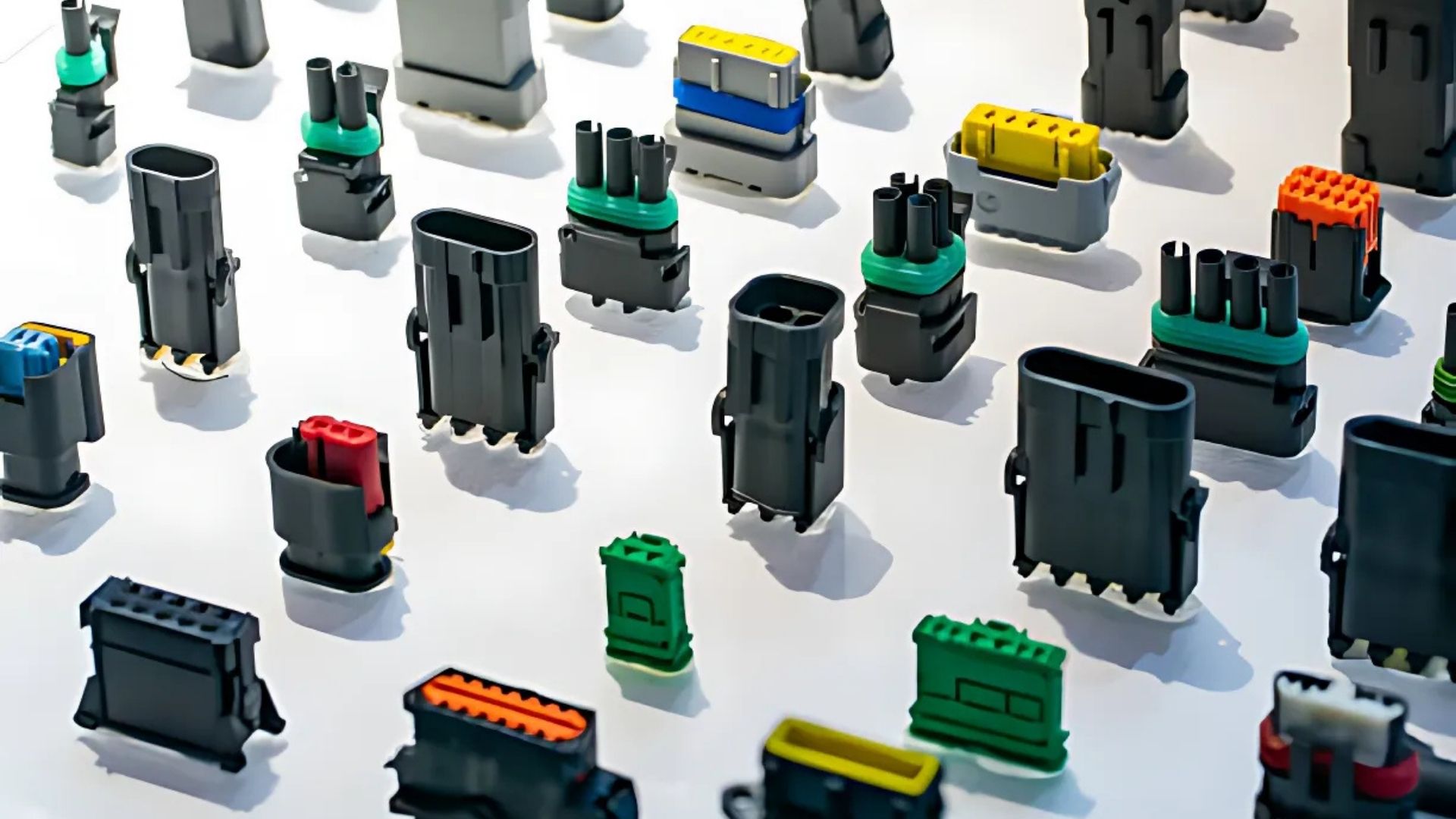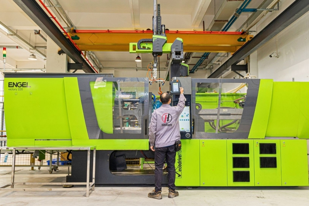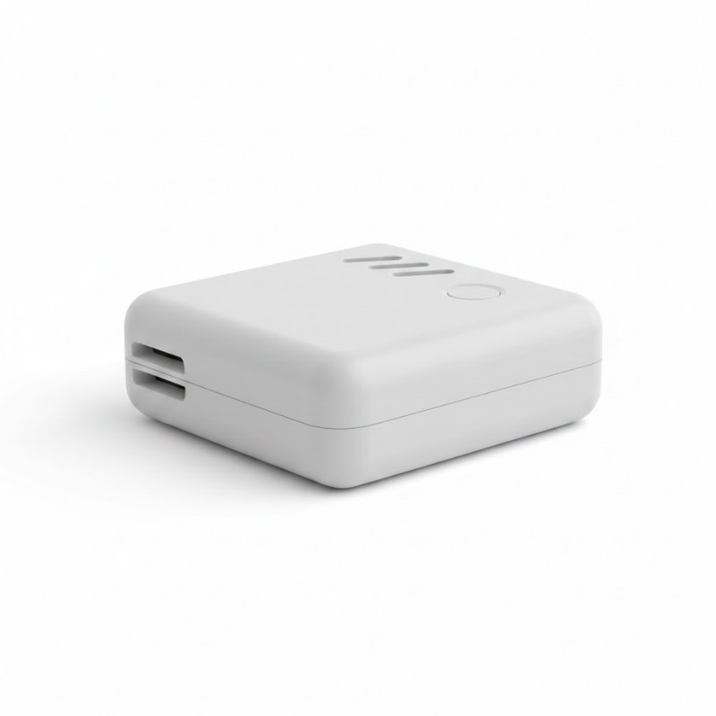
DFM — design for manufacturability — is the review that happens before tooling starts, while a change still costs a drawing revision instead of a mold revision. A part that molds right the first time is rarely lucky. It is usually a part whose designer, or whose supplier’s DFM review, caught the risks early: the wall that changes thickness halfway across the part, the rib that is too heavy for the wall it supports, the gate in the wrong place, the tolerance tighter than the process can hold. This guide explains what a serious DFM review checks, why each check matters, and what to change when a check fails — so you can read a supplier’s DFM feedback and tell whether it is real engineering or a rubber stamp.
The short version: most molding problems are designed in before molding starts. Injection Molding Defects: What Causes Sink Marks, Warpage, Flash and Short Shots — and How to Prevent Them showed how defects such as sink marks, warpage, flash and short shots each point back to a cause in the design, the material, the mold or the process — and that the lasting fix is DFM first, then tooling, then process. This post is the other half of that story: the design half. Get the design right and the tool, the material and the process all have an easier job. Get it wrong and no machine setting will fully save the part.
What a DFM review actually is — and what it is not
A DFM review is a structured check of a part design against the realities of injection molding: can this geometry fill evenly, cool evenly, eject cleanly and hold its dimensions, in this material, at this volume, on a real tool? The output should be specific and drawable — move this gate, thin this boss, add draft here, relax that tolerance — each change with a reason attached. If a review comes back with only general praise, or with a list of problems and no proposed changes, it has not done its job.
What a DFM review is not: it is not a redesign of your product, and it is not a promise that nothing can go wrong. A reviewer who has never seen your assembly cannot decide what a surface must look like or which dimension is truly critical — only you can. The review’s job is to show you where the design fights the process, and what the trade-offs are, so you can decide with the facts in front of you. That is also why a DFM review works best as a conversation, not a one-way report: the designer explains what matters, the reviewer explains what the mold can and cannot do, and the drawing changes where the two meet.
Haumann’s process puts the DFM geometric risk evaluation before tooling — the review finds the risk while it is still cheap to fix. The scope of a review, and any applicable fees, are confirmed before work begins, so there are no surprises after the drawing is already in the tool shop. To request one, use the Request a DFM Review call to action on the contact page.
The six checks that decide whether a part molds well
A DFM review covers many details, but most of them fall under six headings. Work through them in this order, because the order matters: wall thickness drives cooling, cooling drives warpage, gate placement drives fill, and tolerances decide what all of it costs.
| Check | What it asks | What goes wrong if it fails |
|---|---|---|
| 1. Wall thickness | Is the wall even, and is it right for the material? | Sink marks, warpage, long cooling, short shots |
| 2. Draft | Can the part leave the mold without dragging? | Scuffs, drag marks, ejection damage, sticking |
| 3. Ribs and bosses | Are they sized to the wall, and cored where they should be? | Sink marks opposite the feature, voids, warpage |
| 4. Gates and flow | Does material reach every corner evenly? | Weld lines on visible faces, short shots, uneven fill |
| 5. Tolerances | Is every tolerance the process can actually hold? | Costly tooling, rejected parts, arguments over measurement |
| 6. Material | Is the grade right for the part’s job and environment? | Warpage, cracking, wrong stiffness, drying problems |
Read the table as a checklist for your next drawing review. The sections below take each check in turn, explain why it matters, and say what a good fix looks like.
1. Wall thickness: keep it even, and keep it honest
Wall thickness is the first thing a DFM review looks at, because it drives almost everything else. Plastic shrinks as it cools, and a thick section holds more material and stays hot longer than the thin wall around it — so it keeps shrinking after the surface has set. That is the mechanism behind sink marks, which Injection Molding Defects: What Causes Sink Marks, Warpage, Flash and Short Shots — and How to Prevent Them explains in full: the surface above a thick section is pulled inward as the material underneath contracts, and the mark appears opposite ribs, bosses and other heavy features.
The design answer is to keep wall thickness as even as possible across the part, and to change it gradually where it must change, with smooth transitions instead of sharp steps. A wall that jumps from thin to thick in one place creates a sink risk in that place and a cooling difference that can warp the part. Where a section genuinely needs to be stronger, the answer is usually not a thicker wall — it is a rib, a gusset or a change of material. A thicker wall also cools more slowly, which lengthens the cycle and costs money on every single part, so even walls are a cost decision as well as a quality decision.
What to ask in a review: which is the thickest section on this part, and what sits opposite it on the visible surface? Where does the wall change thickness, and is the transition gradual? If the answer is a single heavy section with no plan for it, that section is the first thing to redesign.
2. Draft: the angle that lets the part leave the mold
Draft is a small taper on the walls of a part, so the part releases cleanly from the mold instead of dragging against it as it ejects. Without draft, the part scrapes along the mold surface on its way out — leaving scuffs and drag marks on visible faces, stressing the part, and in the worst case sticking in the tool and stopping the run. With draft, the part pulls away from the mold surface the moment it starts to move, and ejection becomes a clean, repeatable step instead of a fight.
How much draft a part needs depends on the surface finish, the material and the depth of the feature — a highly polished cosmetic surface and a deep, thin wall need more care than a textured, shallow one — so a DFM review does not quote one number for every part. It looks at each face and asks: is there enough taper here for this finish and this depth, and does the taper run in the right direction, away from the mold? Draft also has to be considered together with the parting line, because the taper on each side of the part must suit the half of the mold it comes from. A part that is drafted correctly on one side and not the other will still drag on the undrafted side.
What to ask in a review: which faces have no draft, and why? On a textured or polished cosmetic face, is the draft enough for that finish? And has the draft been applied before the dimensions were set — because adding draft after tolerancing changes the dimensions at the top and bottom of the wall, and a part dimensioned without draft in mind will not measure as drawn once draft is added.
3. Ribs and bosses: strength without the sink
Ribs and bosses are how a molded part gets its strength without becoming a solid block of plastic. A rib is a thin wall standing off the main wall; a boss is a raised, usually round feature that a screw or insert goes into. Done well, they make a part stiff and functional while keeping the walls thin and even. Done badly, they are the single most common cause of sink marks on visible surfaces.
The rule is proportion. A rib or boss that is far heavier than the wall it stands on will sink the surface opposite it, however well the machine is set — Injection Molding Defects: What Causes Sink Marks, Warpage, Flash and Short Shots — and How to Prevent Them makes the same point from the defect side, and the fix is the same from the design side: size the rib and the boss to the wall, core out a solid boss so it is not a lump of material, and use fillets and gradual transitions where the feature meets the wall instead of a sharp corner. A cored boss — hollowed out from behind, with a wall of its own — gives the screw something to hold while keeping the material volume close to the wall it stands on. Gussets, small triangular supports at the base of a rib or boss, add stiffness without adding a heavy section, and they cost nothing but a little drawing time.
What to ask in a review: for every rib and boss, what is its size relative to the wall, and is the boss cored? Which visible surface sits opposite each one? If a boss is solid and heavy, ask what it would take to core it — and what the sink mark on the other side will cost if it stays solid.
4. Gates and flow: where the plastic enters decides where the problems land
The gate is where molten plastic enters the cavity, and its position decides how the material flows, where weld lines fall, and whether every corner of the part fills. A gate in the wrong place fills one side of the part before the other, leaves a weld line across a visible surface, or starves a thin section so it never fills at all — the short shot described in ‘Injection Molding Defects: What Causes Sink Marks, Warpage, Flash and Short Shots — and How to Prevent Them’. Gate placement is therefore a design decision, not a tooling afterthought, and it belongs in the DFM review.
A good gate position fills the part evenly, keeps weld lines off visible and highly loaded areas, and gives the thick sections the material they need while they are still hot enough to pack. That usually means gating into a thick section rather than a thin one, and thinking about the flow path the way the plastic will experience it: the longest, thinnest path is the one most likely to freeze early. The number of gates matters too — a large or complex part may need more than one — but every extra gate is another weld line to place carefully, so the review has to weigh fill against appearance and strength together.
What to ask in a review: where are the gates, and where will the weld lines fall? Are any of them on a visible surface or in a thin, loaded section? And what happens to the fill if the material grade changes — because a grade that flows less easily may need a different gate, and a part designed for one grade may not mold in another without a new gate plan.
5. Tolerances: tight where it matters, honest everywhere else
Tolerances are where DFM saves the most money, and where it is most often ignored. Every dimension on a drawing does not need the same tolerance. The dimensions that matter are the ones that affect fit, function or assembly — a bore that a shaft passes through, a face that seals, a hole pattern that must line up with a mating part. Everything else can be looser, and should be, because a tight tolerance on a non-critical dimension buys nothing and costs tooling time, inspection time and rejected parts.
A DFM review should therefore ask, for each tight tolerance: what does this dimension actually do, and can the molding process hold it in this material, at this wall thickness, at this volume? Some tolerances are simply tighter than injection molding can hold reliably, and the honest answer is to redesign the interface — a post-machined feature, a different assembly method, a datum change — rather than to demand a tolerance the process cannot deliver and then argue about measurement. The published case studies show what a well-judged tolerance looks like in practice: the precision lighting endcap case study held ±0.015 in across its critical dimensions, with 11 of 11 dimensions passing at the first trial — a result that came from designing the part and the tool together, not from tightening every number on the drawing.
What to ask in a review: which three dimensions on this part are truly critical, and what happens in the assembly if each one moves? Which tolerances could be relaxed without any effect on fit or function? And how will each critical dimension be measured — because a tolerance is only as good as the measurement that checks it, and a part can pass its own dimensions and still fail the assembly, as ‘Injection Molding Defects: What Causes Sink Marks, Warpage, Flash and Short Shots — and How to Prevent Them’ notes for warpage.
6. Material: the grade is a design decision, not a purchasing decision
Material selection belongs in the DFM review because the grade changes everything the review has already checked. Different grades shrink differently, flow differently, absorb moisture differently and hold tolerances differently — so a wall thickness, gate plan or tolerance that works in one grade may not work in another. Choosing the grade late, or changing it after the tool is cut, is one of the most expensive mistakes in injection molding.
The review should ask what the part has to do: its mechanical loads, its temperature range, its chemical exposure, its appearance, its regulatory environment and its expected life. Then it should ask whether the proposed grade meets those needs with margin — and what that grade demands in return, such as drying before molding or a particular wall thickness range. Haumann’s material-specific guides show how deep this goes for a single grade: the PA66-GF30 drying, warpage and tolerance post covers that grade’s drying and warpage behavior in detail, because a glass-filled nylon that is not dried and handled correctly will warp no matter how good the design is. The DFM review is where that conversation happens — before the tool exists, not after the parts start warping.
What to ask in a review: why this grade, and what would change if it changed? Does the grade need drying, and is that in the process plan? And has anyone checked the grade against the part’s real environment — not just its room-temperature data sheet?
Putting it together: the DFM review as a program, not a document
A DFM review is most valuable when it is treated as the start of the program, not a document that gets filed. The review’s findings should flow into the tool design — gate positions, cooling layout, ejection — and then into the first-article check, where the parts are measured against the mating part and the assembly, not only against the drawing. That is how a program reaches a result like the one in the precision lighting endcap case study: a small PC ABS FR part, 40 × 25 × 11 mm, that passed 11 of 11 dimensions at its first trial, with its appearance passed as well. First-trial passes do not happen by accident. They happen when the design, the tool and the process were all planned from the same review.
The same discipline applies at the other end of the scale. The metal parts replaced by injection molding case study shows a metal LED endcap redesigned as a molded PC ABS FR part and qualified at its first trial — a change of material and process that only works when the DFM review has thought through the new geometry, the new tolerances and the new failure modes, instead of copying the metal part’s drawing into plastic. And when the program reaches volume, the high-volume injection molding guide explains how the same DFM decisions — even walls, balanced gates, a held process window — are what keep thousands of parts the same as the first ones.
If you are sending a design out for molding, the most useful thing you can do before the quote is to ask for the DFM review and to read it properly: which checks passed, which failed, what changes are proposed and why. A supplier who can answer those questions clearly is a supplier who has thought about your part. A supplier who cannot is telling you something too — and it is better to hear it before the tool is cut than after the first parts arrive.
Frequently Asked Questions: DFM for Injection Molding
DFM — design for manufacturability — is a structured review of a part design against the realities of injection molding: whether the geometry fills evenly, cools evenly, ejects cleanly and holds its dimensions, in the chosen material, before tooling is cut.
Before tooling starts, while a change still costs a drawing revision instead of a mold revision. A review after the tool is cut can only suggest workarounds; a review before it can change the design.
The main checks are wall thickness, draft, ribs and bosses, gate placement and flow, tolerances, and material selection — in that order, because wall thickness drives cooling, cooling drives warpage, and gate placement drives fill.
A thick section holds more material and stays hot longer than the thin wall around it, so it keeps shrinking after the surface has set, pulling the surface inward. The fix is design-led: even walls, ribs and bosses sized to the wall, and cored bosses.
It depends on the surface finish, the material and the depth of the feature — there is no single number for every part. A DFM review checks each face for enough taper in the right direction, for its finish and depth.
A solid, heavy boss or rib on a thin wall, with a visible surface opposite it. It guarantees a sink mark that no machine setting can fully fix — and it is usually the cheapest mistake to fix on the drawing.
No. Tighten only the dimensions that affect fit, function or assembly, and relax the rest. A tight tolerance on a non-critical dimension buys nothing and costs tooling time, inspection time and rejected parts.
Only partly. A review of an existing tool can suggest gate, cooling or process changes, but the geometry is already fixed — which is why the review belongs before tooling, not after.
Yes. Different grades shrink, flow and absorb moisture differently, so a wall thickness, gate plan or tolerance that works in one grade may not work in another. Material selection belongs in the review, not after it.
Project ownership, engineering review and communication are managed by Haumann’s team in Houston, Texas, which directs the DFM reviews, tool configuration validations and final quality checks, while scalable offshore facilities handle high-volume mass production under one quality standard. That gives US OEM teams a local, accountable partner with global manufacturing capacity behind it.