In a high-voltage electric vehicle battery, a busbar joint carries operating current while facing vibration and repeated thermal cycling. A small change at that interface can affect efficiency, local temperature, and long-term reliability.
Visual appearance alone is not enough for a resistance-welding busbar application. A joint may look uniform while hiding incomplete consolidation, contamination, or excessive resistance. Reliable production requires measurable strength, low contact resistance, and consistency across shifts and material lots.
Haumann’s automated EV production lines use resistance butt welding in an end-to-end configuration. The process differs from resistance spot welding, which joins overlapping sheets or tabs at localized points. In butt welding, two conductive elements meet face-to-face, electrical resistance creates heat at the interface, and controlled upset pressure consolidates the joint across the material section.
This article explains the process, common sources of variation, online monitoring, and in-house destructive pull testing.
What Busbar Resistance Butt Welding Does
An EV battery module uses busbars and conductive interconnects to distribute current between cells, terminals, and module connections. Every joint must support the electrical and mechanical demands defined by the customer.
Resistance butt welding joins two conductive components end-to-end. Before the cycle begins, the parts are positioned so their prepared end faces meet squarely at a controlled interface. The tooling maintains alignment, electrical current passes through the contact area, and resistance at the interface generates localized heat. As the material reaches the required condition, upset pressure forges the two ends together and consolidates the joint.
The process does not use an overlapping joint. Its effectiveness depends on end-face condition, energy stability, component alignment, and controlled upset during the cycle.
A successful butt joint creates a continuous conductive path with adequate mechanical integrity. It must carry current with minimal added resistance and withstand the specified operating loads.
The process window can be narrow. Too little effective energy or insufficient upset can leave an incompletely consolidated interface. Too much energy can enlarge the heat-affected region, distort the components, or transfer unnecessary heat into nearby features. Production control therefore has to balance joint formation with thermal discipline.
Why Weld Quality Matters in High-Voltage Battery Assemblies
Electrical resistance at a busbar joint creates heat when current flows. As contact resistance rises, local heating increases, especially during high-load events.
A properly formed joint keeps resistance within the customer’s limit. Voids, incomplete bonding, contamination, or uneven contact can raise resistance and create hot spots that visual inspection may miss.
Battery assemblies experience vibration, thermal expansion, contraction, and handling loads. A weak joint may loosen, crack, or change electrically, increasing resistance and further heating.
Excess heat input presents a different risk. The welding cycle should deliver enough energy to form the butt joint without unnecessarily heating surrounding conductors, insulation, fixtures, or nearby battery components. The acceptable range is bounded on both sides: under-welding can produce a weak or resistive interface, while over-welding can damage the assembly or reduce dimensional control.
Weld quality is defined by validated mechanical and electrical results, not appearance alone.
The Two Core Metrics: Joint Strength and Contact Resistance
A busbar weld must satisfy two different performance requirements. The first is mechanical joint strength. The second is electrical contact resistance. Neither metric can replace the other. Customer specifications and the approved quality plan remain controlling, while ISO 15614-13 provides a broader framework for qualifying upset resistance butt-welding procedures.
Mechanical Joint Strength
Mechanical strength is verified by loading a sample under a defined test method until it reaches the required load or fails. For an end-to-end resistance butt weld, the exact fixture, loading direction, sample geometry, and acceptance value must match the customer specification and the approved quality plan.
The result is not only a maximum force value. The failure location also matters. Separation at the welded interface can indicate that the joint is the limiting feature. Failure in the parent material, while the welded interface remains intact, shows that the surrounding material reached its limit before the joint separated.
The target is program-specific. A responsible technical article should not present one universal force requirement for every EV busbar. Material type, conductor size, joint geometry, assembly loads, and validation requirements all influence the acceptance criteria.
Contact Resistance
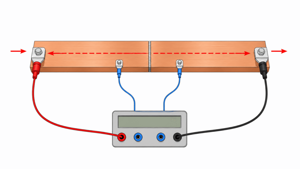
Contact resistance measures the electrical contribution of the welded interface. Because busbar joints operate at very low resistance levels, production and validation measurements should use a method suitable for low-resistance testing. A four-wire Kelvin arrangement separates the current-carrying leads from the voltage-sensing leads, reducing the influence of lead and contact resistance on the result.
The measured value is compared with the approved upper limit and trended over time. A stable average is useful, but the distribution matters too. A gradual shift toward the limit can indicate process drift before parts begin to fail acceptance testing. A four-wire Kelvin arrangement separates the current-carrying leads from the voltage-sensing leads, reducing the influence of lead and contact resistance on the result.
Why Both Metrics Are Required
A joint can perform well mechanically and still have unacceptable electrical resistance. It can also show low resistance while lacking the mechanical robustness required for vibration and handling. Qualification must therefore demonstrate both outcomes.
The relationship is not always linear. Increasing energy may improve consolidation up to a point, but additional energy beyond the validated window may cause distortion, material expulsion, or an oversized heat-affected zone. Reducing energy can improve thermal control, but too little may leave an incomplete interface. The validated process window is the range where both strength and resistance remain acceptable.
What Causes Resistance Butt Weld Variation
Most production problems can be traced to a limited group of variables. The important task is to control them before they create a trend or a rejected lot.
End-Face Contamination
Oxides, oils, coating residue, and handling contamination change the electrical and thermal behavior of the contact interface. They can make heating less predictable and interfere with uniform consolidation. Cleaning and material handling upstream of the welding cell are therefore part of weld quality, not separate housekeeping activities.
Poor Fit-Up and Alignment
The two end faces must meet with the geometry established during validation. If the components are not square, parallel, or correctly positioned, the real contact area can differ from the intended area. Heating may then concentrate in one region, and upset may occur unevenly across the joint.
Fixtures must control position without introducing damage or variation. End preparation, part tolerances, and tooling condition should all support repeatable face-to-face contact.
Material Variation
Conductor alloy, cross-section, hardness, coating, and surface condition can vary within supplier tolerances. Those changes affect resistance, heating behavior, and the way material responds to upset pressure. A process qualified with one material condition should not be assumed to behave identically with every incoming lot.
Incoming inspection, supplier controls, and lot traceability help the production team understand whether a process shift began at the welding cell or entered with the material.
Tooling and Contact Wear
Current delivery and mechanical alignment depend on stable tooling contacts, fixtures, cables, and interfaces. Wear can change contact geometry, resistance, force transmission, or part position. Preventive maintenance should be based on validated intervals and observed process trends rather than waiting for an obvious failure.
Energy, Timing, and Upset Variation
A welding recipe includes more than one setting. Delivered energy, cycle timing, pressure sequence, part position, and upset behavior work together. Changing one variable can affect the others. That is why process changes should be evaluated through controlled validation instead of isolated setpoint adjustments on the production floor.
A validated recipe cannot be transferred blindly from one busbar design to another. Changes in material cross-section, alloy, end-face area, coating, or thermal mass alter how energy enters the interface and how the material responds to upset pressure. Even a small geometry change can shift the balance between heating and consolidation. New part numbers, supplier changes, and approved engineering revisions should therefore be reviewed against the original qualification basis before production continues under the same limits.
Real-Time Monitoring Without Assuming One Signal
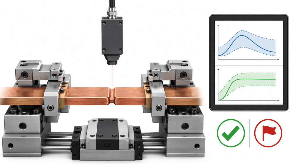
Welding systems monitor different signatures according to machine design and application. Signals may include energy, displacement, electrical data, thermal response, or force. The chosen strategy must correlate with acceptable physical weld results.
Haumann’s automated EV resistance butt welding lines use laser and energy-based online monitoring. Energy monitoring records the energy delivered during the cycle. Laser measurement tracks upset displacement, which is the physical change that occurs as the heated interface consolidates under pressure.
These signals are evaluated against a validated envelope developed by correlating monitored signatures with pull-test results, contact-resistance measurements, and acceptable joint condition.
A signature outside the approved range shows that the cycle differed from validated behavior. The control plan can flag the part, contain production, and trigger the required response.
Trend data can reveal wear, contamination, fixture movement, or material change before a nonconforming part appears. Teams can respond to drift before a failed sample forces action.
Online monitoring is therefore a production-control tool, not a substitute for destructive testing. It checks each cycle against known behavior, while periodic physical testing confirms that the known behavior still produces acceptable joints.
Monitoring limits also need a documented reaction plan. A flagged cycle should lead to a defined action, such as part segregation, fixture inspection, material verification, maintenance review, or additional physical testing. The response should match the type and severity of the deviation. Clear rules reduce operator judgment calls and prevent questionable assemblies from moving downstream while the cause remains unknown. When a trend approaches a limit without crossing it, the team can schedule corrective work before output is interrupted.
This closed loop matters during launch and mature production. Qualification creates the initial relationship between settings, monitored signals, and test results. Ongoing sampling confirms that relationship after normal wear, maintenance, material changes, and environmental variation. If the correlation weakens, the process envelope must be reviewed rather than treated as permanent.
This approach also supports faster troubleshooting because engineers can compare monitored behavior with physical test results, material records, and maintenance history before adjusting the validated welding process.
In-House Destructive Pull Testing
Haumann performs destructive pull testing in-house under a defined sampling plan. Selected samples are loaded in a controlled fixture until the required endpoint or failure condition is reached.
The test records both force and failure mode. These results must be reviewed together because neither a load value nor a failure description provides the complete picture alone.
Testing frequency should be defined in the approved control plan and may include qualification, start-up, scheduled production, material changes, maintenance events, and abnormal monitoring signals.
Results should be trended, not stored only as pass-or-fail records. Changes in force or failure mode can reveal drift, while links to machine, recipe, material lot, and batch support audits and root-cause analysis.
Destructive testing verifies mechanical performance. Contact-resistance testing verifies electrical performance. Together, they confirm that the online monitoring envelope remains connected to actual joint quality.
Butt Welding, Spot Welding, and Other Busbar Joining Processes
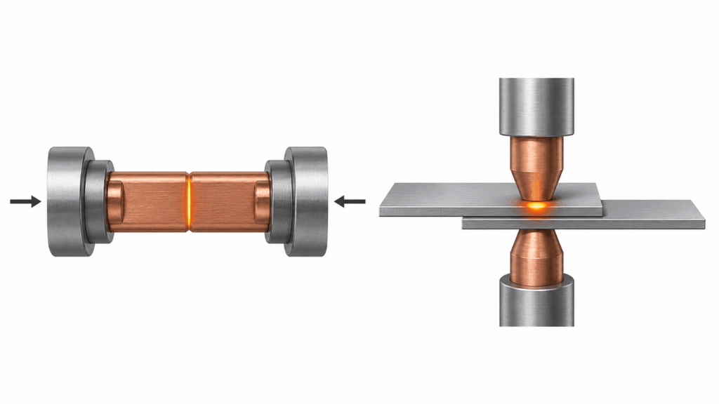
Resistance butt welding and spot welding belong to the same process family, but their joint configurations differ.
Butt welding joins two components end-to-end across a prepared interface. The parts are aligned face-to-face, current creates heat at the interface, and upset pressure consolidates the joint. This is the configuration used on Haumann’s automated EV production lines.
Spot welding joins overlapping materials at localized points, often in thin-tab or sheet configurations. Calling an end-to-end line spot welding misrepresents its tooling, joint behavior, and validation needs.
Ultrasonic welding uses high-frequency mechanical motion to create a solid-state bond and can suit selected thin or dissimilar conductive materials.
Laser welding uses a focused beam and can suit geometries requiring noncontact energy delivery or limited tool access. Its controls and qualification approach differ from resistance welding.
No process is best for every battery architecture. Selection depends on material, geometry, access, electrical demand, cycle time, heat sensitivity, inspection strategy, and customer requirements. One assembly may use heat staking for plastic features and welding for conductive interconnects.
Repeatability, Traceability, and Tier 1 Readiness
Producing one strong, low-resistance joint is a development result. Producing the same result throughout a production year is a manufacturing capability.
A mature process defines the recipe, monitoring ranges, material requirements, fixture controls, maintenance intervals, sampling plan, reaction plan, and traceability. Operators need a clear response when a cycle falls outside the envelope, and quality teams must identify what requires containment.
Traceability should connect each assembly to the material lot, machine, tooling station, recipe revision, shift, production batch, monitoring result, and verification records required by the program.
The purpose is faster, evidence-based decisions. When results shift, the team should compare material, equipment, maintenance, and process history without reconstructing events from memory.
For an EV Tier 1 customer, this discipline shows that a system, not occasional inspection, controls quality. Monitoring supports each cycle, physical tests verify performance, maintenance controls wear, and traceability supports investigations.
Consistency at volume is the real capability. Objective records must show that production remained within validated requirements.
Routine review of capability data helps distinguish random variation from a sustained shift, supporting better decisions about containment, maintenance, requalification, and supplier follow-up before customer requirements are directly affected.
Frequently Asked Questions
Busbar resistance welding uses electrical resistance at a joint interface to generate localized heat while pressure supports joint formation. In resistance butt welding, two conductive components are joined end-to-end. Resistance spot welding uses a different configuration and joins overlapping materials at localized points.
Visual inspection can identify surface damage, misalignment, or obvious deformation, but it cannot reliably confirm internal consolidation, mechanical strength, or low contact resistance. Process monitoring and physical verification tests are needed to evaluate those characteristics.
Monitoring depends on the equipment and validated control plan. Haumann’s automated EV lines use laser measurement to track upset displacement and energy-based monitoring to record delivered energy. The measured signatures are compared with an approved process envelope.
Haumann verifies mechanical performance through in-house destructive pull testing under a defined sampling plan. The test records the applied force and the failure mode, allowing the team to evaluate both the measured result and where the sample failed.
Very low joint resistance can be measured with a four-wire Kelvin method. Separate current and voltage-sensing connections reduce the influence of test-lead resistance, providing a more accurate measurement of the welded interface.
Yes. Excessive heat can distort conductors, enlarge the heat-affected region, damage nearby materials, or transfer unwanted heat into surrounding components. The validated process window must prevent both under-consolidation and excessive heat input.
No. Butt welding joins two components end-to-end across their contact faces. Spot welding joins overlapping materials at one or more localized points. The tooling, joint geometry, monitored behavior, and validation approach are not interchangeable.
OEM readiness requires more than welding equipment. It includes a validated process, cycle-by-cycle monitoring, defined destructive and electrical testing, preventive maintenance, reaction plans, material controls, and traceable production records.
EV busbar welding quality depends on the complete process. End-face preparation, alignment, energy delivery, upset behavior, monitoring, testing, maintenance, and traceability all influence the result.
Haumann Group manufactures precision components and assemblies for high-voltage EV battery applications, including resistance butt welding. Contact our engineering team to discuss joint geometry, validation, monitoring, and scalable production.
Need Reliable EV Busbar Welding at Production Scale?
Haumann Group supports high-voltage EV battery programs with precision resistance butt welding, in-house destructive pull testing, laser and energy-based process monitoring, and production traceability.
Talk to our engineering team about your busbar joint design, validation requirements, quality targets, and high-volume production needs.