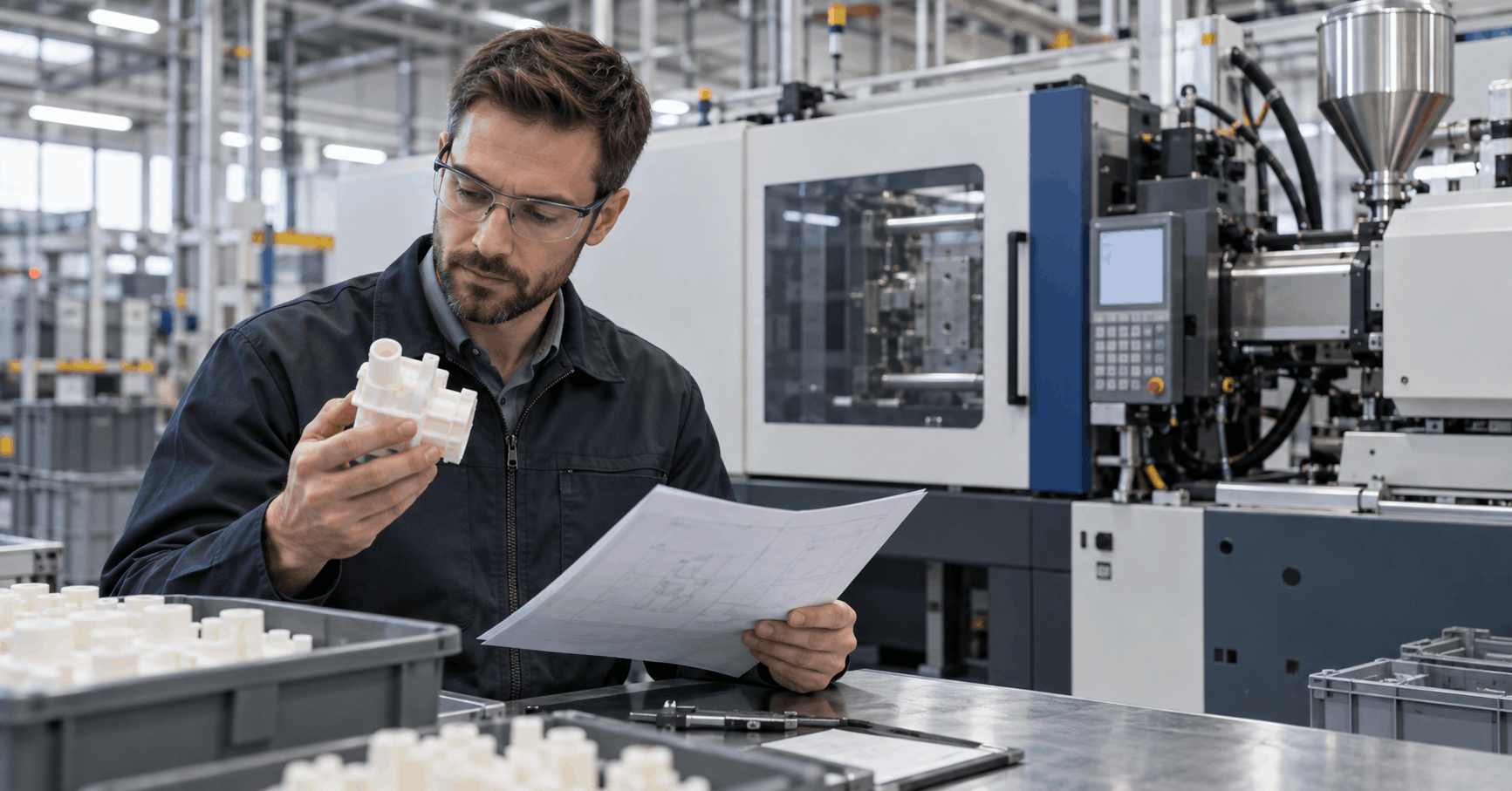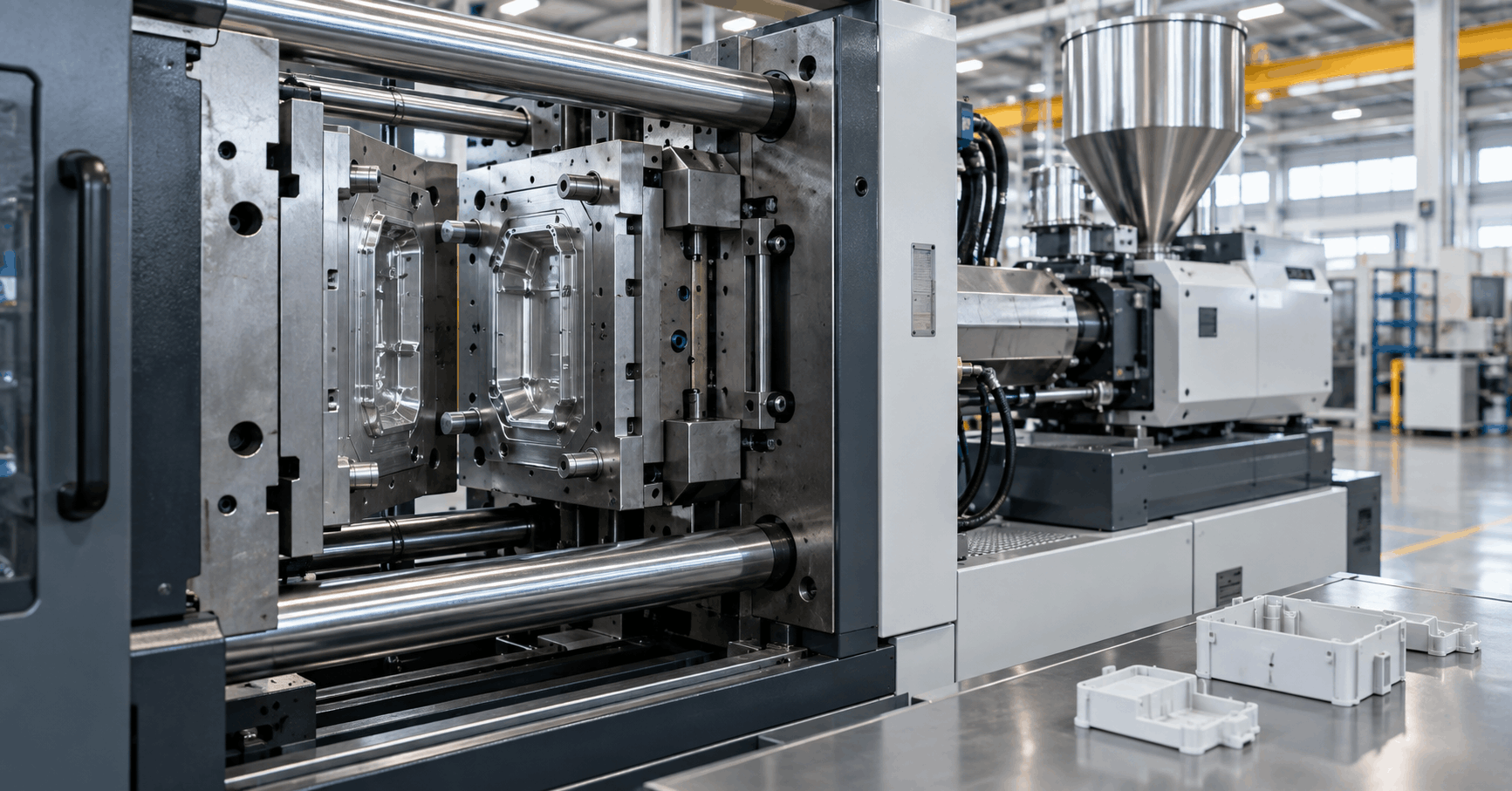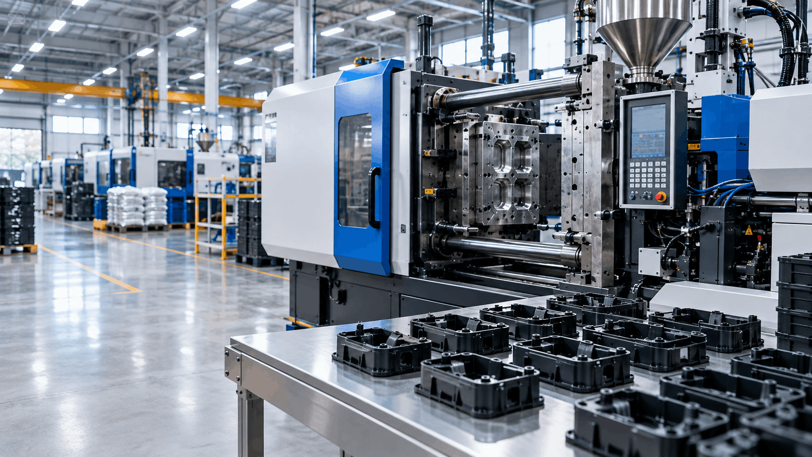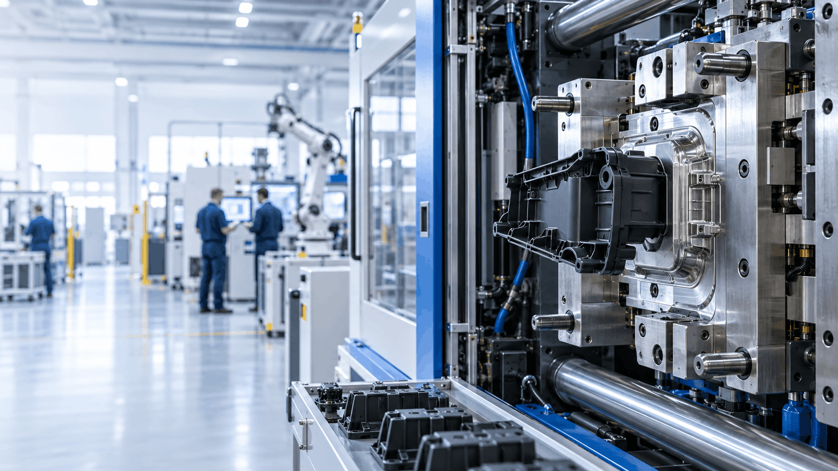
In a high-voltage EV battery assembly, a heat-staked joint is not a cosmetic detail. It is a structural element holding busbar carriers, insulation frames, and end plates in position for the operational life of the pack — through thermal cycling, through vibration, through mechanical load, in an environment where a displaced component is a high-voltage risk rather than a warranty complaint.
When that joint fails, it does not fail quietly at inspection. It fails in the field.
The difficulty is that the material best suited to these components, PA66-GF30, is also among the least forgiving materials to heat stake. Get the process window wrong, and the polymer degrades. The joint still looks correct. It still measures correctly. And it is already compromised.
This article sets out why that happens, the three distinct ways degradation manifests, and what genuine process control looks like at scalable OEM manufacturing volumes — where the engineering challenge is not producing one sound joint, but producing the hundred-thousandth joint identical to the first.
What the Heat Staking Process Is
Heat staking joins a thermoplastic component to a mating part by softening a moulded plastic boss with controlled heat, then forming it under pressure into a head that mechanically locks the assembly together. Once the material cools and stabilises, the joint is permanent. No fasteners. No adhesives. No secondary hardware introduced into the assembly.
For EV battery module production, this is precisely what the application demands.
No conductive hardware in a high-voltage environment. A metal fastener inside a busbar carrier assembly introduces a creepage and clearance consideration that simply does not exist with a formed plastic joint. Removing metal from the joint removes an entire category of electrical design constraint.
No added mass. Pack-level weight is under permanent pressure in EV design. A heat-staked joint adds nothing that was not already moulded into the part.
No cure time, no chemistry. Adhesive bonding introduces cure cycles, surface preparation requirements, shelf-life management and environmental sensitivity. Heat staking produces a completed joint within the cycle, with no consumables and no chemistry to control.
Cycle times compatible with OEM volume. Multi-head automated heat staking equipment can form many joints simultaneously in a single controlled cycle, which is what makes the process viable at automotive production rates rather than prototype quantities.
The apparent simplicity is deceptive. The heat staking process is a thermal event applied to a polymer with a narrow processing window, and the difference between a sound joint and a degraded one is frequently invisible to the naked eye and undetectable by dimensional inspection.
Why PA66-GF30 Is Unforgiving
PA66-GF30 is polyamide 66 reinforced with 30% glass fibre by weight. It is specified for battery module components because it delivers what the application requires: mechanical strength under sustained load, dimensional stability across thermal cycles, heat resistance appropriate to a pack environment, chemical resistance, and the electrical insulation properties needed for high-voltage separation.
Every characteristic that makes it right for the part makes it difficult to stake.
Glass fibre does not soften
This is the fundamental point and the one most often underestimated. When heat is applied, only the polyamide matrix flows. The glass fibres remain rigid. They do not melt, do not reform, and do not redistribute themselves obligingly into the new head geometry.
The consequence is that the material must flow around a rigid reinforcement structure while forming. Compared with an unfilled polymer — where the entire mass softens and flows homogeneously — the behaviour is fundamentally different, and heat staking parameters developed for unfilled material do not transfer.
Polyamide 66 is hygroscopic
PA66 absorbs atmospheric moisture readily. This is a well-understood property of the polymer, and it is not a defect. But it has a direct consequence for any thermal process applied to it.
Heat absorbed moisture rapidly, and it flashes to steam within the polymer. That drives hydrolytic chain scission — the water molecules break the polymer chains at a molecular level. The damage is permanent; it reduces mechanical strength, and it is not recoverable by any subsequent process step.
A component that has been sitting in ambient humidity before staking is, thermally speaking, not the same component that came out of the mould. Treating it as though it were is one of the most common routes to degraded joints in production.
The thermal window is narrow
Below the window, the matrix does not flow adequately, and the head forms incompletely — geometrically present, structurally hollow.
Above it, the polymer begins to degrade thermally. Chain scission, oxidation, loss of molecular weight, loss of strength.
Between those two limits sits a band that must be held consistently across every cycle, every staking head, every shift, and across the natural lot-to-lot variation in incoming material. The width of that band is what makes PA66-GF30 demanding. It is not that a good joint is hard to achieve once. It is that it is hard to achieve every time.
Fibre orientation is directional and permanent
Glass fibres align with material flow during injection moulding. That alignment determines the mechanical anisotropy of the boss — where it is strong, where it is comparatively weak, and how it will respond when reformed under heat and pressure.
That orientation was set in the moulding tool. Heat staking does not reset it. Which means the staking process must be designed with an understanding of how the boss was moulded in the first place — the two processes are not independent.
The Three Failure Modes
Degradation in heat staking presents in three distinct ways. Each has a different root cause. Treating them as a single problem is how manufacturers end up adjusting parameters at random and chasing symptoms.
1. Thermal degradation — the failure you can sometimes see
Excess heat, or adequate heat held for excessive duration, breaks the polymer chains. In severe cases it is visible: discolouration, browning, scorching, a glazed or blistered surface on the formed head.
The head may still be geometrically correct. It may still pass a visual check by an operator who has been told to look for a well-formed head. But the molecular structure has been damaged and the mechanical performance of the joint has dropped, sometimes substantially.
The genuinely dangerous version is the marginal case — where degradation has initiated but has not yet produced visible discolouration. The joint is measurably weaker and nothing on the production line indicates it.
2. Under-consolidation — the failure you cannot see at all
Insufficient heat, insufficient dwell, or insufficient pressure leaves the polymer inadequately flowed. The head forms in outline but never achieves proper consolidation with the material beneath it. Internal voids. Poor bonding at the interface. A joint that is, in effect, hollow.
There is no visual indication whatsoever. The part looks right. It measures right. It passes.
In a battery module context this is the most hazardous defect class that exists. The component ships, is assembled into a pack, is installed in a vehicle, and fails under thermal cycling and vibration months or years into service — at which point it is a field failure in a high-voltage assembly, with all the traceability and recall exposure that implies.
This single failure mode is the reason heat staking cannot be controlled by inspection. It has to be controlled by process.
3. Dimensional distortion — the failure that propagates
Heat applied to a glass-reinforced part induces localised internal stress. If pressure is released before the heat has cooled and dimensionally stabilised, the material relaxes, the stress finds its way out, and the part warps.
In a busbar carrier, dimensional drift is not cosmetic. It affects the positional accuracy of high-voltage connections. It affects the geometry that establishes electrical clearance. It affects whether downstream assembly operations locate correctly.
And unlike the first two failure modes, this one propagates — a distorted carrier does not fail in isolation; it disturbs everything assembled to it.
Where Process Control Actually Happens
Preventing all three failure modes comes down to controlling the same set of variables, consistently, at volume. What follows is our methodology. It is not a parameter sheet — specific values are application-dependent and are established during process validation for each part.
Material state before the part reaches the station
Because PA66-GF30 is hygroscopic, moisture state is managed upstream of staking. This is the single most preventable cause of hydrolytic degradation, and it is addressed before the component ever reaches the staking head.
This is a manufacturing discipline rather than a machine setting, and it is often the difference between a process that behaves predictably and one that produces unexplained variation between batches. When a heat staking process is described as “inconsistent,” incoming material state is the first place to look.
Thermal control at the interface, not at the machine
What matters is not the temperature the heat staking machine is set to. It is the temperature the polymer actually reaches at the joint interface, held for the duration required for the matrix to flow around the glass reinforcement — and no longer than that.
This distinction is where a great many heat staking parameters go wrong. An open-loop process aims at a temperature and assumes it was achieved. A closed-loop process monitors what is actually happening at the interface and responds within the cycle.
At production volume, tooling heats, ambient conditions shift, material lots vary. An open-loop process drifts through the window over the course of a shift. A closed-loop process stays inside it.
Pressure as a profile, not a value
Pressure in heat staking is not a single number applied for a fixed time. It is a profile across the cycle:
During softening — how force is applied as the polymer begins to flow, and whether it is applied too early, before the material is ready to move.
During forming — how force is held as the head takes shape and consolidates with the material beneath.
During cooling — and this is the phase most frequently compromised — how force is maintained while the joint cools and stabilises.
Releasing pressure while the material is still above its transition point is a direct and common cause of dimensional drift. The cooling phase under pressure is not idle time at the end of the cycle. It is part of the joint formation, and shortening it to gain cycle time is one of the most expensive false economies in the process.
Designing the joint before it exists
A significant proportion of heat staking failures are designed in, long before any production part is made.
Boss geometry. Wall thickness. Draft. The volume of material available to form the head, relative to the head geometry the application requires. Whether the boss can be moulded without a sink or a void at its base. Whether fibre orientation in the as-moulded boss supports the direction of load the finished joint will carry.
Heat staking design guidelines matter most at the point where the component is still a CAD model — because at that stage, changing them costs nothing. Once the tool is cut, each of those decisions becomes a process constraint that must be worked around.
Where we are engaged during design, this is where the most durable improvements are made — and where the difference between a robust process and a marginal one is usually decided.
Repeatability is the actual capability
A single good joint proves nothing.
A validated heat-staking process proves that the hundred-thousandth joint is equivalent to the first — across every head on a multi-head machine, across shifts, across operators, across incoming material lots, and across a production year.
At OEM volumes, consistency is the capability. Anything else is a demonstration.
What This Means for VDA Battery Module Components
For VDA-specified battery module carriers, busbar frames and end plate assemblies, the requirement is not simply a joint that holds. It is a joint that holds under a defined, monitored and auditable process — with traceability back to the conditions under which it was formed.
This is the point at which heat staking stops being a joining operation and becomes part of a quality system.
A Tier 1 customer qualifying a supplier is not asking whether we can heat stake PA66-GF30. Anyone can produce one acceptable joint. They are asking whether we can demonstrate that every staked joint in every shipped module was produced inside a validated process window — and whether we can prove it when the audit comes.
That is the standard the process has to be built to, and it is the standard that separates a supplier who can make the part from a supplier who can be trusted with the programme.
Frequently Asked Questions
Heat staking is a joining process in which a moulded thermoplastic boss is softened with controlled heat and formed under pressure into a head that mechanically locks two components together. It is widely used in EV battery module assembly for busbar carriers, insulation frames and end plates, where fastener-free, dimensionally stable joints are required in a high-voltage environment.
Its 30% glass fibre reinforcement does not soften with heat, so only the polyamide matrix flows and must move around a rigid fibre structure. The material is also hygroscopic, meaning absorbed atmospheric moisture can drive hydrolytic degradation when heated. Combined with a narrow thermal processing window, this leaves very little margin for error.
Through management of material moisture state before staking, closed-loop thermal control at the joint interface rather than open-loop timing, a managed pressure profile that maintains force through the cooling phase, and boss geometry designed for the process from the outset rather than adapted to it afterwards.
Not reliably. Severe thermal degradation may show as discolouration, but under-consolidated joints — where insufficient heat or pressure has left internal voids — typically show no visual indication at all. The part looks correct and measures correctly. This is why validated process control, rather than visual inspection, is the only dependable safeguard.
Both form a thermoplastic boss into a locking head, but they generate the heat differently — thermal staking applies heat directly, while ultrasonic staking generates it through high-frequency mechanical vibration. For glass-filled materials such as PA66-GF30, the choice depends on the specific joint geometry, the material, and the consistency required at volume.
Yes. Multi-head automated heat staking equipment is well suited to scalable OEM manufacturing, provided the process is properly validated and monitored. The engineering challenge is not producing one sound joint — it is producing identical joints consistently across production volume, shift after shift.
It introduces no metal hardware into a high-voltage environment, which removes an entire class of electrical clearance considerations. It adds no mass to the pack. And it produces a completed joint within the cycle, with no cure time and no consumable to manage.