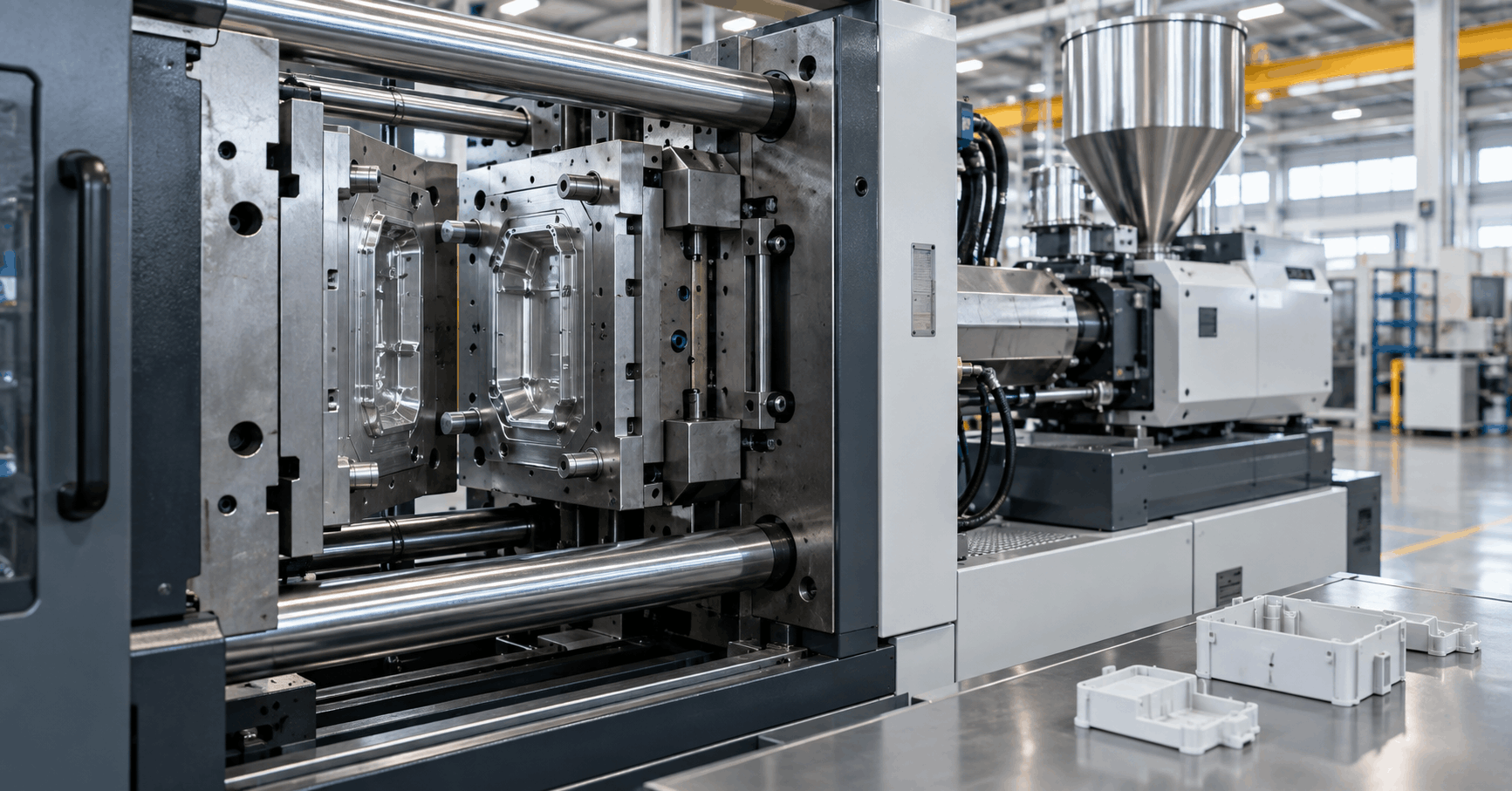
How Automotive Plastic Components Are Made: From DFM to OEM Approval
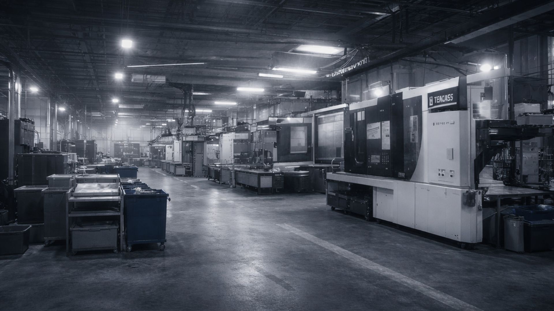
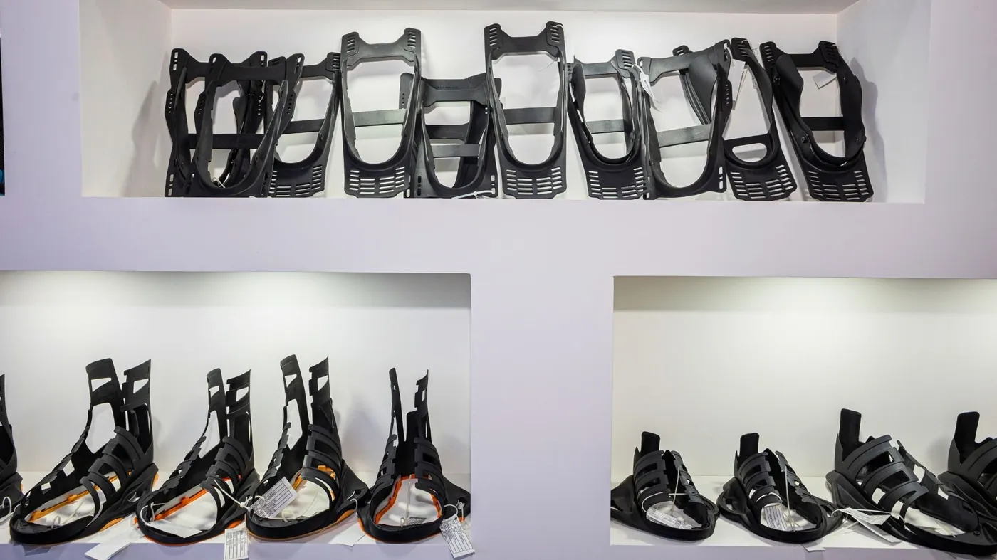
Open the door of any modern car and most of what you touch is plastic — the dashboard carrier behind the trim, the air vents, the seat mechanisms, the connectors and housings under the hood. A typical vehicle contains well over a hundred kilograms of molded plastic, and almost every gram of it passed through the same disciplined route: design review, hardened steel tooling, controlled molding, and a formal approval process before the first production part could ship.
That route is what separates automotive plastic parts manufacturing from general molding. The molding itself is rarely the hard part. The hard part is proving — with documents, measurements and process data — that part number one hundred thousand will match part number one. This guide walks through how automotive plastic components are actually made, stage by stage, from the first DFM review to OEM approval.
Quick answer: the six stages of automotive plastic parts manufacturing
Automotive plastic components are made in six stages:
- DFM for automotive — the part design is reviewed and adjusted for molding, tolerances and assembly before any steel is cut.
- Tooling — a hardened steel injection mold is designed and built, with cavitation matched to the program’s annual volume.
- Material selection — an automotive-grade resin (commonly PP, PA66-GF30 or PC/ABS) is specified for the part’s environment and load case.
- Molding — parts are produced inside a validated process window, with statistical process control (SPC) watching the critical characteristics.
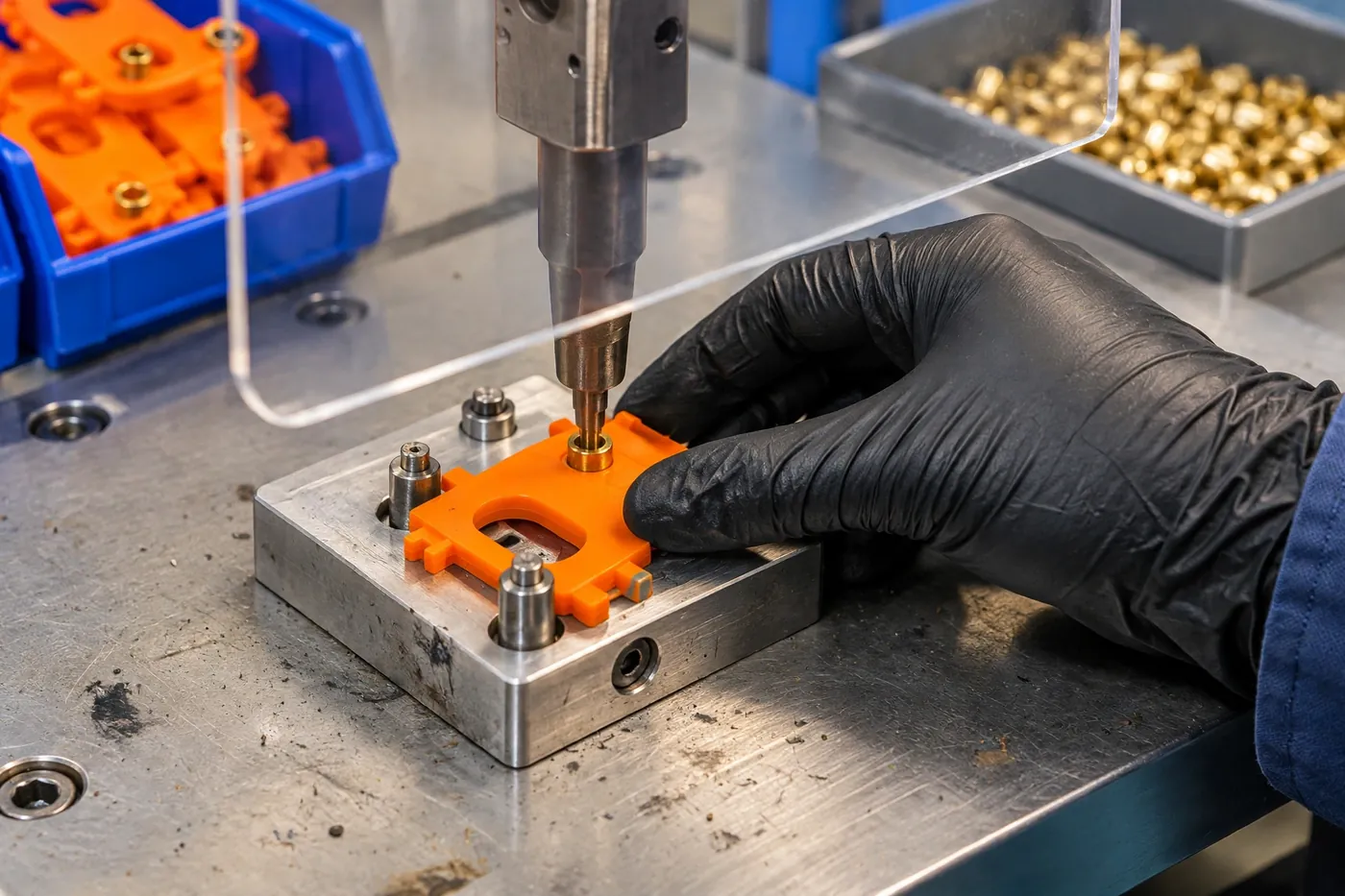
- Secondary operations and assembly — welding, staking, insert fitting and sub-assembly turn moldings into finished components.
- Validation and PPAP — samples are measured against every drawing requirement and submitted for the customer’s Production Part Approval Process sign-off.
Skip or rush any one of these stages and the program usually pays for it later — in tooling rework, dimensional disputes, or a delayed launch.
Stage 1: DFM for automotive — where programs are won or lost
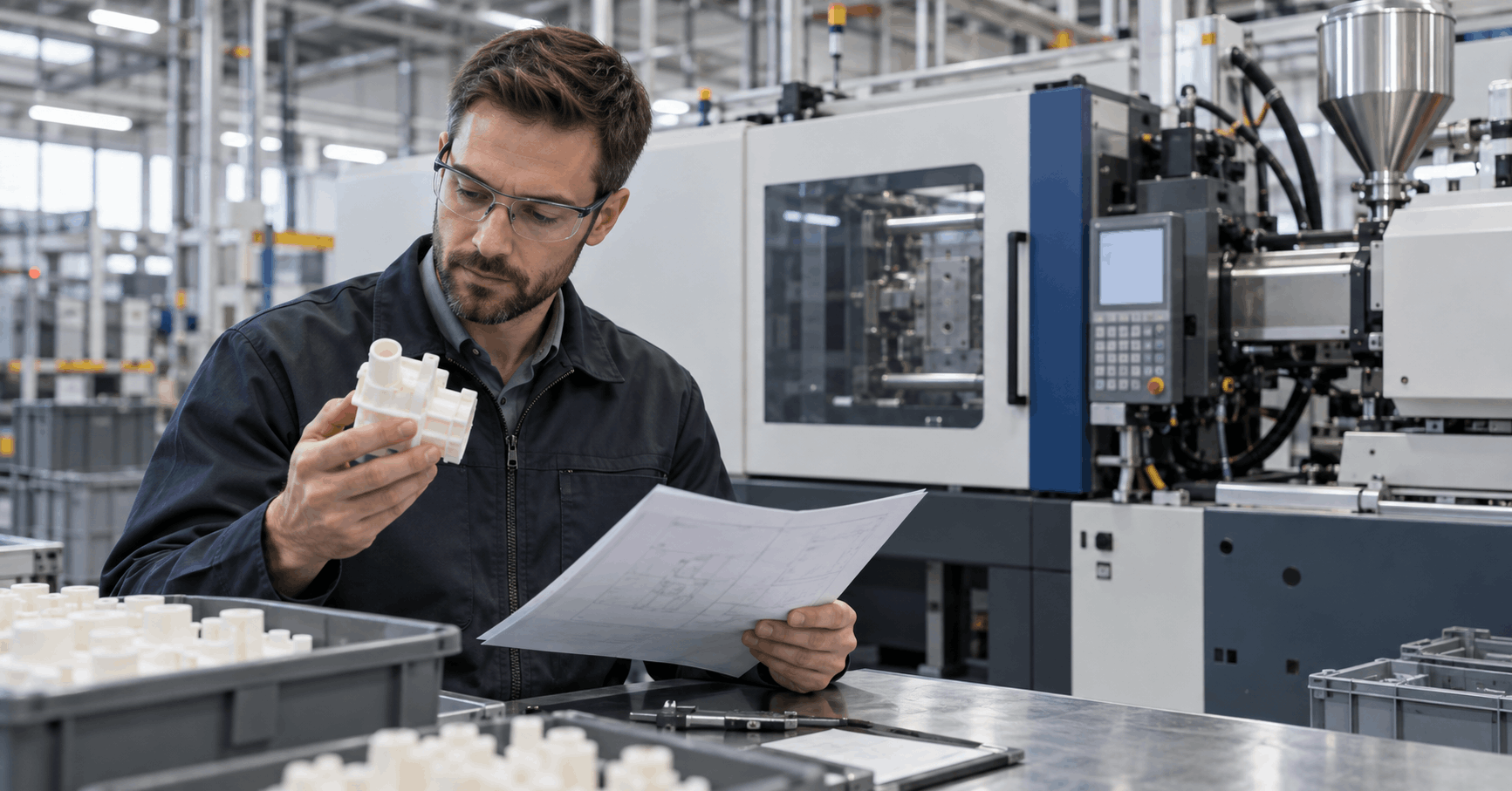
DFM (design for manufacturability) is a structured review of the part design before tooling starts. For automotive work it goes further than checking whether a part can be molded. The review asks whether the part can be molded repeatedly, at rate, inside tolerance, for the life of the program — which on a vehicle platform can be many years.
A typical automotive DFM review covers:
- Wall thickness and transitions — uniform walls fill and cool evenly; abrupt thickness changes cause sink marks, voids and warpage that no process setting can fully cure.
- Draft and parting lines — enough draft for clean ejection without drag marks on visible (Class A) surfaces.
- Ribs, bosses and snap features — sized to add stiffness and assembly strength without creating sink on the show surface.
- Gate location — where the plastic enters decides weld-line position, and a weld line in a loaded or visible area is a defect designed in at the CAD stage.
- Tolerances and CTQs — critical-to-quality characteristics are identified, and tolerances that the process cannot hold are renegotiated before they become PPAP failures.
- Shrinkage and material behaviour — glass-filled materials shrink differently along and across the flow direction; the tool design has to compensate from day one.
Why does automotive DFM differ from consumer-product DFM? Because the consequences differ. An under-hood part must survive heat, vibration and chemical exposure for the vehicle’s life; an interior part must match colour and grain across dozens of mating components from different suppliers. Catching a problem in the DFM review costs a meeting. Catching it after the tool is built costs a tooling modification — and catching it after PPAP submission can cost the program.
Stage 2: Tooling — the mold is the process
Once DFM is signed off, the design moves into steel. Automotive tooling decisions are driven mainly by annual volume, part geometry and the approval timeline:
- Cavitation — a low-volume service part may run in a single-cavity tool; a mainstream program justifies multi-cavity tooling so output, cycle time and part cost balance. Cavitation is an economic decision made once and lived with for years.
- Runner system — hot runners reduce waste and improve fill balance on multi-cavity tools; cold runners remain sensible for simpler parts and lower volumes.
- Actions — undercuts and side features need slides, lifters or collapsible cores, each adding build time, maintenance and process risk that DFM should have minimised.
- Cooling design — cooling channels decide cycle time and dimensional stability more than almost anything else in the tool; warped parts are very often cooling problems.
- Steel and surface finish — hardened tool steels for long automotive program lives, with polishing or texture matched to the part’s appearance class.
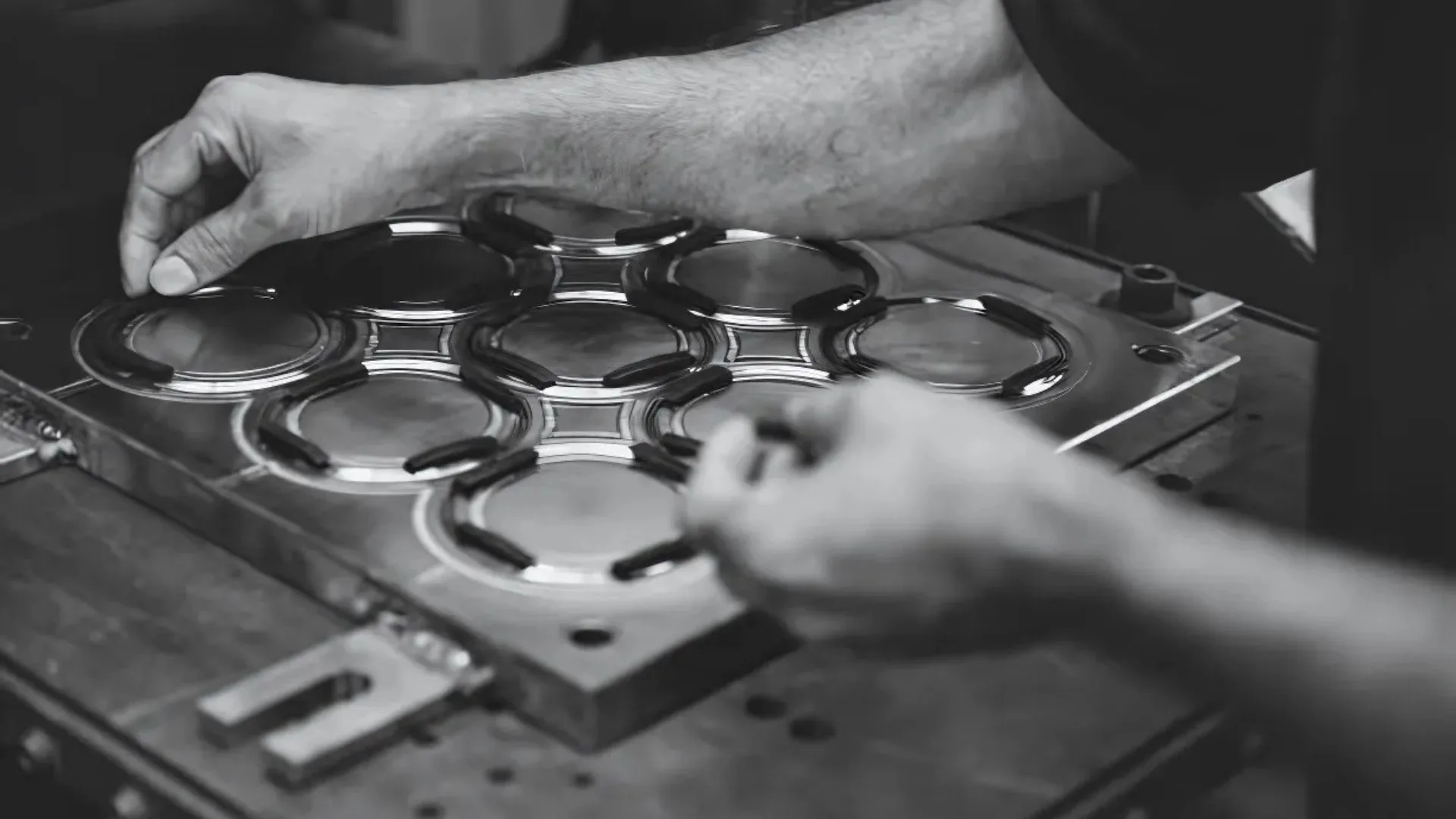
The tooling stage is also where the measurement plan begins: the CTQs agreed in DFM become the checkpoints for first-article inspection and PPAP. Programs that treat tooling as a pure purchasing exercise — lowest price, fastest promise — tend to rediscover these decisions during validation. For a deeper look at how tooling choices are made, see our guide to injection mold tooling.
Stage 3: Materials — PP, PA66-GF30 and PC/ABS do most of the work
Three resin families cover the majority of automotive plastic components:
- Polypropylene (PP) — the workhorse for interior trim, door panels, bumpers and fluid reservoirs. Light, chemically resistant, inexpensive, and available in filled and impact-modified grades for colder climates.
- PA66-GF30 (glass-filled nylon) — the under-hood and structural choice: engine covers, intake components, fan shrouds, brackets and pedal assemblies, where heat resistance and stiffness under load matter. Glass content changes both strength and shrinkage behaviour, which is why PA66-GF30 injection molding needs its own process discipline.
- PC/ABS blends — interior housings, bezels, glove-box and console components that need impact strength with a better surface finish than PP typically delivers.
Around those three sit the specialists: TPE and TPU for seals and soft-touch surfaces, POM for gears and clips, PPS and other high-temperature resins for the hottest under-hood zones. Whatever the resin, automotive production adds controls that general molding often skips — approved material sources, lot traceability, controlled drying for moisture-sensitive resins like PA66, and regrind limits written into the process documentation. A material substitution mid-program is not a purchasing shortcut; it is a change that requires customer notification and usually re-approval.
Stage 4: Molding at automotive scale — consistency is the product
With the tool built and the material specified, production molding begins — and the goal changes. Prototyping asks, “can we make a good part?” Automotive production asks, “can we make the same part, at the quoted rate, shift after shift?”
That consistency is built, not inspected in afterwards:
- A validated process window — melt temperature, injection profile, packing, cooling time and clamp force are established during tool trials and locked as the approved process, not left to operator preference.
- SPC on critical characteristics — CTQs identified in DFM are measured on a defined sampling plan and charted, so drift is caught while parts are still inside tolerance instead of after a failed sort.
- Cavity discipline on multi-cavity tools — cavities are identified and monitored individually; a balanced fill across cavities is what makes multi-cavity output interchangeable.
- Automation and handling — part removal, degating and packing are standardised so cosmetic surfaces are not damaged by variable manual handling.
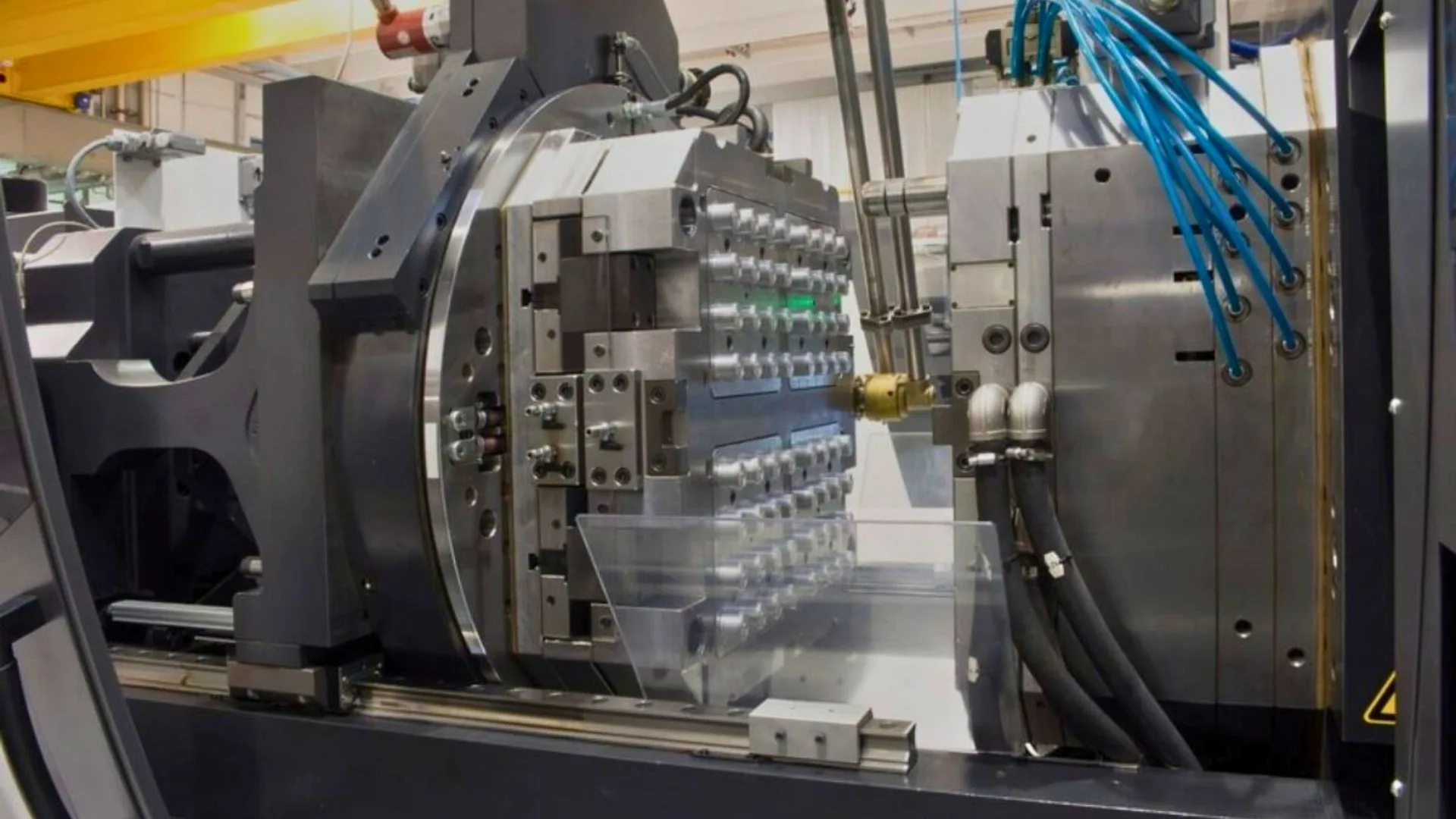
Scale changes the economics and the risk at the same time: the same process discipline that runs a niche program runs a mainstream one, but the cost of an undetected drift grows with every hour of production. How volume changes tooling and process decisions is covered in our overview of high volume injection molding.
Stage 5: Secondary operations — from molding to finished component
Many automotive components leave the press as finished parts. Many more do not. Secondary operations turn moldings into assemblies the OEM line can fit directly:
- Joining — heat staking and ultrasonic welding attach brackets, membranes and mating housings without fasteners or adhesives.
- Insert and hardware fitting — threaded inserts, clips, springs and metal stampings fitted at the molding cell or a dedicated assembly station.
- Sub-assembly — multi-part mechanisms (vents, handles, latch assemblies) built and function-tested before packing.
- Finishing — degating, deflashing and, where specified, painting, printing or chrome-effect treatments through qualified partners.
Each secondary operation adds its own controls — weld parameters, pull tests, function checks — and its own section in the control plan. Choosing between the two main plastic joining methods is a design decision with cost and quality consequences; our comparison of heat staking vs ultrasonic welding works through it in detail.
The quality system OEMs actually require
Everything above happens inside a quality management system, and for automotive work that system has a name: IATF 16949, the automotive QMS standard built on ISO 9001 and administered under the International Automotive Task Force’s global oversight scheme. Haumann produces under IATF 16949 and ISO 9001 systems — but the certificate alone is not what OEMs approve. They approve the working disciplines the standard demands:
- APQP (Advanced Product Quality Planning) — the phased planning framework published by the AIAG that sequences design, tooling, process design and validation so quality is planned in rather than inspected in.
- FMEA and control plans — failure modes are analysed before production, and every CTQ gets a defined measurement method, frequency and reaction plan.
- MSA and SPC — the measurement systems themselves are proven capable (gauge R&R), and process capability on critical characteristics is demonstrated statistically.
- PPAP (Production Part Approval Process) — the evidence package submitted to the customer: dimensional layout results, material certification, process flow, FMEA, control plan and capability studies. Only after PPAP approval may production parts ship.
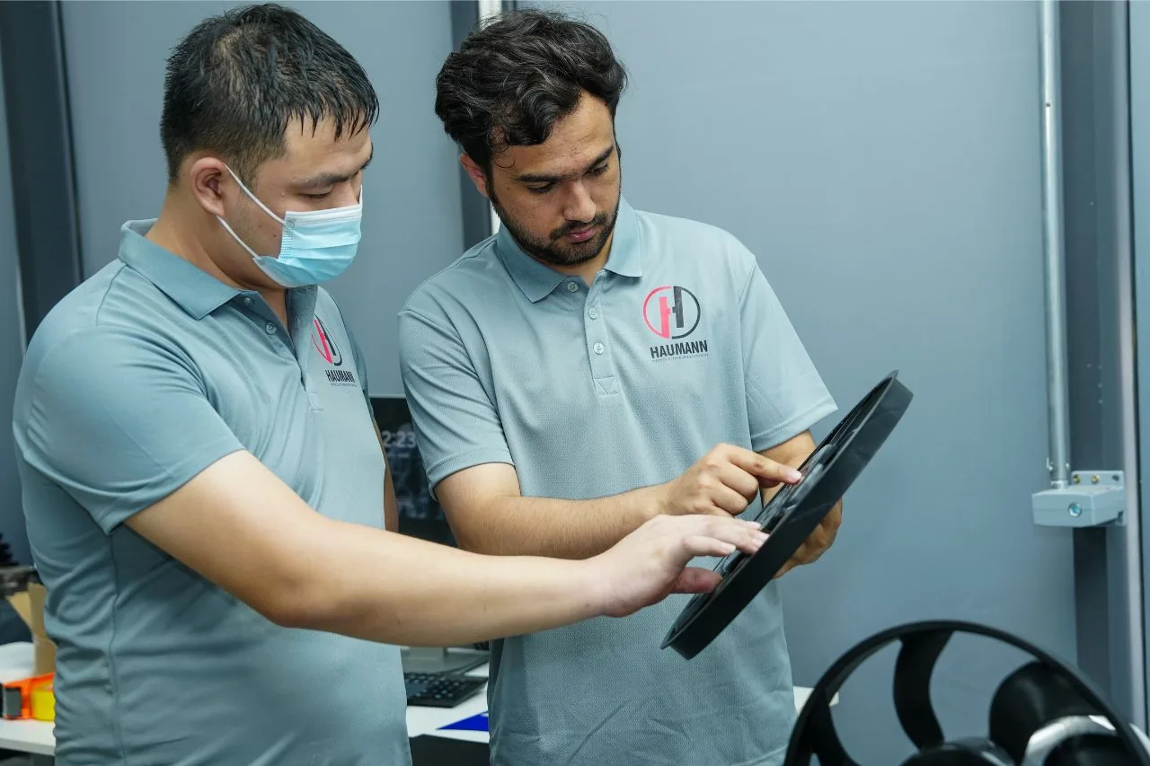
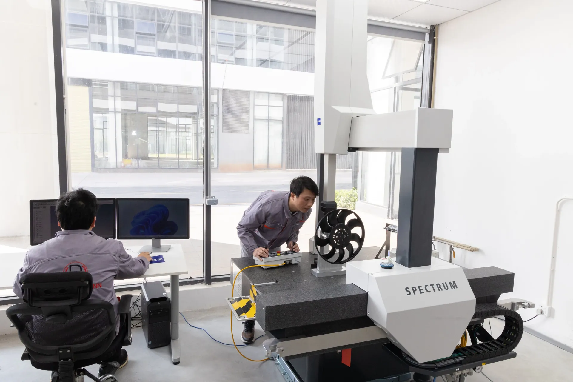
What this looks like in practice: the radiator cooling fan in the photograph below is produced by Haumann for an automotive program — a component whose balance and dimensions are safety-relevant at speed. Before release, production samples are verified on a coordinate measuring machine (CMM), and the critical characteristics agreed with the customer are the same ones monitored in series production. That is the difference between a supplier who has a quality certificate and one who works to it: the measurement discipline is visible on the shop floor, part by part.
What drives cost and lead time
Buyers often ask for the cost and timeline of an automotive component before sharing a drawing — and the honest answer is that both are set by the drawing itself. The main drivers:
- Part size and complexity — undercuts, actions and tight cosmetic requirements add tooling cost and build time.
- Cavitation versus annual volume — more cavities cost more up front and less per part; the right balance depends on the program’s real volumes.
- Material — resin choice can multiply raw material cost several times between commodity PP and engineering grades.
- Tolerance and CTQ count — every critical characteristic adds measurement, capability work and documentation.
- Secondary operations and PPAP level — assembly content and the depth of the approval package both add time before first shipment.
For the full breakdown of how these drivers interact, see our pillar guide to injection molding cost. The practical shortcut is simpler: the earlier a manufacturer sees the real CAD file and volumes, the earlier these drivers stop being estimates.
Frequently Asked Questions
Quoting an automotive program?
Request a technical DFM review — send your STEP file and annual volume, and our Houston-area engineering team in Conroe, Texas will review manufacturability, flag risks before tooling, and quote the program on real inputs. Request a technical DFM review.